Table of Contents

Related Manuals for MultiDyne SilverBack V

Summary of Contents for MultiDyne SilverBack V
- Page 1 CONFIGURATION AND OPERATION MANUAL SilverBack V CAMERA-MOUNTABLE FIBER OPTIC TRANSMISSION SYSTEM 10 NEWTON PLACE HAUPPAUGE, NY 11788 USA (877) 685-8439 / (516) 671-7278 / FAX (516) 671-3362 sales@multidyne.com www.multidyne.com...
-
Page 2: Table Of Contents
SilverBack V Camera-Mountable Fiber Optic Transmission System TABLE OF CONTENTS TABLE OF CONTENTS __________________________________________________________________ 2 IMPORTANT SAFETY INSTRUCTIONS _____________________________________________________ 4 LASER SAFETY INFORMATION __________________________________________________________ 6 OVERVIEW __________________________________________________________________________ 7 SilverBack V Family ___________________________________________________________________ 7 SilverBack V Camera Unit ______________________________________________________________ 7 SilverBack V Base Unit _________________________________________________________________ 8... - Page 3 SilverBack V Camera-Mountable Fiber Optic Transmission System Camera Ethernet Connections _____________________________________________________ 16 Intercom, Tally, and GPIO Connections ______________________________________________ 16 Audio Connections ______________________________________________________________ 16 Serial Data Connections __________________________________________________________ 17 Frame Controller Connection ______________________________________________________ 17 CONNECTIONS: CAMERA UNIT _________________________________________________________ 18 Camera Unit Connectors ______________________________________________________________ 18...
-
Page 4: Important Safety Instructions
SilverBack V Camera-Mountable Fiber Optic Transmission System Audio Output Configuration _______________________________________________________ 44 Intercom Configuration ___________________________________________________________ 45 Reference and Timecode Configuration ______________________________________________ 46 Serial Data Configuration _________________________________________________________ 46 Base Unit Network Configuration ___________________________________________________ 47 IP Address Settings ______________________________________________________________ 47 Firmware Updates _______________________________________________________________ 49... - Page 5 SilverBack V Camera-Mountable Fiber Optic Transmission System or objects have fallen into the apparatus, the apparatus has been exposed to rain or moisture, does not operate normally, or has been dropped. • Throughout this manual, a number of warning and caution notes may be presented to alert the user to important safety or operating information.
-
Page 6: Laser Safety Information
SilverBack V Camera-Mountable Fiber Optic Transmission System LASER SAFETY INFORMATION This unit is classified as a CLASS 1 LASER PRODUCT according to EN60825-1 (EU) and FDA 21CFR 1040.10 (USA). Class 1 laser products are considered safe and do not result in biological hazard if used according to these instructions. -
Page 7: Overview
The SilverBack V can transport up to one 12G-SDI, two 6G-SDI, or four 3G-SDI signals from a camera to its rack-mounted base station, with one return path. Full camera control is provided by the camera manufacturer’s control panel via serial or a 10/100/GigE Ethernet path. -
Page 8: Silverback V Base Unit
SilverBack V Base Unit The SilverBack V base unit interfaces up to two cameras and accessories via lightweight tactical fiber cable or with SMPTE hybrid fiber cable to deliver all of your signals and the power to run your cameras and accessories. -
Page 9: Installation
AC POWER 2: Camera 2 and base unit power Camera Unit Installation Connect the SilverBack V adapter unit to your camera's Anton Bauer or V-mount battery connector. Click into place to ensure that the unit is secure. Base Unit Installation Before cabling, ensure that the SilverBack V base unit is clear of wiring, equipment, and other obstructions. - Page 10 SilverBack V Camera-Mountable Fiber Optic Transmission System Integrating SilverBack V with Your Facility A. Tactical Fiber Cable — Camera Powered Locally B. SMPTE Hybrid Fiber — Standard Internal “Juice” Power Supply C. SMPTE Hybrid Fiber — External “Juice-48 or Juice-60” Power Supply Page ©...
- Page 11 SilverBack V Camera-Mountable Fiber Optic Transmission System Maximum powered hybrid fiber distance varies and is determined by the size of the hybrid cable and the overall system power requirements. Power consumption of the camera, viewfinder, lens, and any other accessories will affect maximum available power at any given distance.
-
Page 12: Connections: Base Unit
SilverBack V Camera-Mountable Fiber Optic Transmission System CONNECTIONS: BASE UNIT The following section describes connections to the base unit. Depending on the type of SilverBack V system ordered, some of the signal types may not be available. Base Unit System Example: SB5-B4K1-SPPJ-UB2R-2... -
Page 13: Neutrik Opticalcon Duo Hybrid Fiber Connector Systems
Systems with Neutrik opticalCON DUO connectors typically provide both fiber-optic connectivity to the camera and power to the SilverBack V camera unit. Connect the camera units to these ports using opticalCON DUO cabling. It is recommended to power off the base unit, where possible, before connecting hybrid fiber cable to the camera unit. -
Page 14: St & Molex Connector Systems
Camera 1 Camera 2 The Molex connector on the SilverBack V chassis is a five-pin male Molex Mini-Fit Jr p/n 39-01-4053 (MDCON04787) or equivalent. This configuration requires Molex p/n 39-00-0041 (MDCON04799) crimp pins. The mate for the chassis connector on a breakout cable is Molex Mini-Fit Jr p/n 39-01-4051 (MDCON04818) or equivalent. -
Page 15: Signal I/O Connections
Secondary SDI Connections The SilverBack V base unit is equipped with one or more secondary SDI paths, which function as camera sends, returns, or both. These SDI connections only support data rates up to 3G (they are not 6G or 12G capable). -
Page 16: Camera Ethernet Connections
Intercom, Tally, and GPIO Connections Each camera chain in the SilverBack V base unit has a dedicated DB25 connector for intercom, tally, and GPIO connections. This connector follows the standard pinout used by Sony and Panasonic CCUs and supports 2-wire or 4-wire intercom systems. -
Page 17: Serial Data Connections
LANC. 10' long, DB9 male to 2.5mm female jack. Frame Controller Connection The frame controller in the SilverBack V base unit can be accessed via its 10/100 Mbps Ethernet port. Connect this port to your facility network using Cat5e/Cat6 cabling. -
Page 18: Connections: Camera Unit
The following section describes connections to the SilverBack V camera unit. Depending on the type of system ordered, some of the signal types may not be available. The SilverBack V camera unit is installed on the camera by sliding it onto the camera’s V-mount or Anton Bauer battery plate until it clicks and locks into place. -
Page 19: Camera Reference Sync Connections
If the camera requires SDI reference, connect one of the 3G SDI return outputs on the SilverBack V camera unit to the REF input on the camera. A valid SDI signal must be connected to the base unit on this return path to provide this SDI reference to the camera. -
Page 20: Ethernet Connection
Contact MultiDyne for other adapter cable options. Audio Connections There are two distinct audio connection sections on the SilverBack V camera unit. The first are the two miniXLR MIC/Line inputs adjacent to the intercom headset connector. These analog inputs are used for applications requiring MIC level or the flexibility of switching between MIC and Line level. -
Page 21: Tally And Gpio Connections
Breakout cable, MDR26 to 4 XLR-F & 4 XLR-M Tally and GPIO Connections Tally and GPIO connections on the SilverBack V camera unit are provided on a high-density HD15 connector. The following table describes the available tally and GPIO signals. -
Page 22: D-Tap Power Connections
HDB15 male to 2.5mm male plug D-Tap Power Connections The SilverBack V camera unit is equipped with two D-Tap power output ports for powering external camera accessories. These outputs are 14VDC nominal (12-17VDC) and can each provide up to 5A. -
Page 23: Camera Unit Operation
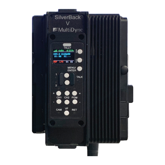
SilverBack V Camera-Mountable Fiber Optic Transmission System CAMERA UNIT OPERATION The control panel on the SilverBack V camera unit provides a simple interface that allows the camera operator to monitor system link and signal status using the SilverBack V display. Push buttons provide navigation assistance to reach menu options and to control intercom push-to-talk, headset volume, and viewfinder settings. -
Page 24: Control Panel Navigation
SilverBack V Camera-Mountable Fiber Optic Transmission System Control Panel Navigation MENU/ENTER • Press to open display main menu. • Press again to select feature UP/DOWN Arrow Buttons • Use to navigate control panel Status pages and sub menus. TALLY Indicator •... -
Page 25: Control Panel: Status Screens
SilverBack V Camera-Mountable Fiber Optic Transmission System CONTROL PANEL: STATUS SCREENS General Instructions The display on the camera unit shows signal and system status on a series of Status pages. The various Status pages are accessed from the Home screen by pressing the UP/DOWN arrow buttons. -
Page 26: Optical Status Screen
SilverBack V Camera-Mountable Fiber Optic Transmission System Data Status D1, D2: D1 and D2 display data activity on the Data 1 and Data 2 serial ports. The indicator will turn green when data activity is detected. Optical Status Screen The Optical Status screen shows the optical receive and transmit power of the internal optics. -
Page 27: Control Panel: Camera Unit Menus
Gearbox Configuration and Operation The gearbox in the SilverBack V camera unit takes the main camera video output and multiplexes it into a single video stream that is sent to the base unit. The gearbox accepts single-link, dual-link, and quad- link video inputs at SMPTE data rates ranging from 1.5G (HD) up to 12G. - Page 28 SilverBack V Camera-Mountable Fiber Optic Transmission System Input Mode Description Single The camera is outputting a single HD, 3G, 6G, or 12G stream. Dual 3G The camera is outputting a dual-link 3G stream (6G total). Dual 6G The camera is outputting a dual-link 6G stream (12G total).
-
Page 29: Audio Settings
SilverBack V Camera-Mountable Fiber Optic Transmission System Viewfinder Configuration and Operation On certain SilverBack V camera unit models, some of the secondary SDI connections can be re-assigned in the Settings menu to connect to a built-in internal viewfinder switch. The camera unit configurations that support a built-in viewfinder switch are shown in the table below. - Page 30 SilverBack V Camera-Mountable Fiber Optic Transmission System Audio Input Settings The SilverBack V camera unit can accept analog line or MIC level inputs on the two miniXLR input connectors and/or analog Line or AES input on the high-density MDR connector. Audio input channels 1 and 2 can be taken either from the miniXLR connectors for MIC/Line applications or from the MDR connector for Line/AES applications.
- Page 31 When selecting DB-AES for inputs 3 and 4, the input is taken from the channel 3 input. Audio Output Settings The SilverBack V camera unit outputs four channels of analog Line-level or AES audio on the high-density MDR connector. Page ©...
- Page 32 Base Unit. Intercom The SilverBack V camera unit uses a 5-pin miniXLR connector to allow use of either single-muff or dual- muff intercom headsets. Headset MIC Gain and Sidetone settings are adjusted from within the Intercom Settings menu. Volume and talkback control are provided using dedicated buttons on the control panel for quick access.
- Page 33 SilverBack V Camera-Mountable Fiber Optic Transmission System MENU > Audio Settings > Intercom Settings > MIC Gain To configure headset Sidetone Gain, navigate to the Audio Settings menu, select Intercom, then select Sidetone Gain. Press Enter to toggle through the available Gain settings and stop at the desired setting.
-
Page 34: Serial Data Settings
6. The microphone will shut off and the TALK LEDs will turn off. Serial Data Settings The SilverBack V camera unit’s Serial Data Channel settings are configured in the Data Settings Menu. Each data port can be configured for RS232/RS422 type data or LANC control data. The factory default setting is RS232/422. - Page 35 SilverBack V Camera-Mountable Fiber Optic Transmission System System Settings, and from the System Settings menu select Timecode. On the Timecode BNC menu, select Direction and press Enter to toggle through the available settings. The Camera timecode settings may also be configured remotely, from the webpage dashboard accessed from the Base Unit.
- Page 36 SilverBack V Camera-Mountable Fiber Optic Transmission System System Information The System Info menu displays the software versions of the unit, as well as provides control of the brightness of the OLED display and LEDs on the control panel. MENU > System Settings > Maintenance > System Info •...
-
Page 37: Saving And Recalling Settings
Note: In order to use the configuration save/recall feature, the microSD card must have a valid, existing cconfig.txt file on it. This file may be obtained from MultiDyne service or can be created on the Base Unit microSD card and then copied to another card for use in the camera unit (see below). -
Page 38: Base Unit Operation
SilverBack V Camera-Mountable Fiber Optic Transmission System BASE UNIT OPERATION The front panel on the SilverBack V base unit provides a simple interface that allows operators to monitor system link and signal status using LEDs and a TFT display. A joystick provides navigation assistance to reach menu options for further status and system configuration. -
Page 39: Base Unit Menus
Select BACK to return to the previous menu. • Select HOME to return to the main menu. SBV System Status The Home screen on the base unit displays a quick overview of SilverBack V system status. Base Unit Root Menu • Status: Fiber/Video/Audio/Intercom/Power •... - Page 40 SilverBack V Camera-Mountable Fiber Optic Transmission System The Base Fiber Rx Status menu displays GBX, 3G or COR for video channels 1 and 2 depending on the cards installed. Base Unit Menu > Status > Fiber > Base Fiber Rx Status The Base Video Status menu displays video resolution for video channels 1 and 2 depending on the cards installed.
- Page 41 SilverBack V Camera-Mountable Fiber Optic Transmission System Base Unit Menu > Status > Intercom > Base Intercom Status The Base Intercom Status menu displays “OK” if there is audio on each respective audio channel. Base Unit Menu > Status > Power > Base Power Status The Base Power Status menu displays Volts and Amps settings for each power supply unit.
-
Page 42: Gearbox Configuration And Operation
SilverBack V Camera-Mountable Fiber Optic Transmission System Gearbox Configuration and Operation The gearbox in each camera chain in the SilverBack V base unit receives the main camera video stream from the camera unit and de-multiplexes it back into its original video format. -
Page 43: Audio Input Configuration
The Gearbox settings may also be configured from the webpage dashboard accessed from the Base Unit. Audio Input Configuration The SilverBack V base unit can accept analog Line-level or AES inputs on the DB25 connector. To configure the base unit audio inputs for Line or AES mode, navigate to the Base Unit Settings menu and select Audio Inputs, then either Analog or AES as desired for each camera chain. -
Page 44: Audio Output Configuration
SilverBack V Camera-Mountable Fiber Optic Transmission System Audio Output Configuration The SilverBack V base unit can output analog Line-level or AES audio on the audio DB25 connector. To configure the base unit audio outputs for Line or AES mode, navigate to the Audio Output Settings Menu and select either Analog or AES as desired for each camera chain. -
Page 45: Intercom Configuration
SilverBack V Camera-Mountable Fiber Optic Transmission System Intercom Configuration The SilverBack V base unit can interface with either 4-wire or 2-wire party-line intercom systems using the intercom/GPIO DB25 connector. To configure the base unit intercom interface for 4-wire or 2-wire mode, navigate to the Base Unit Settings menu and select Intercom, then either 4-wire or 2-wire. -
Page 46: Reference And Timecode Configuration
SilverBack V Camera-Mountable Fiber Optic Transmission System Reference and Timecode Configuration Each camera chain in the SilverBack V base unit has dedicated reference sync and timecode inputs. For dual camera chain systems, either chain’s reference or timecode input may be internally routed to either or both of the camera chains. -
Page 47: Base Unit Network Configuration
Base Unit Menu > Base Network Settings IP Address Settings Four DIP switches on the rear of the SilverBack V chassis are used to set the network address. (Note: Only one switch can be set to the ON position.) DIP Switch # Description DHCP. - Page 48 SilverBack V Camera-Mountable Fiber Optic Transmission System To prevent possible IP address conflicts: • Initially isolate the SilverBack V base unit and your computer from the rest of your network by unplugging all devices except the SilverBack V base unit and your computer. •...
-
Page 49: Firmware Updates
PRO TIP: Physically Identifying a SilverBack V Base Unit in a Facility A LED on the rear of the frame controller card in the chassis can assist in identifying a SilverBack V base unit amidst other rack-mounted gear. Turn this LED on or off from the Frame Ethernet Settings box on the web page. -
Page 50: Saving And Recalling Settings
SilverBack V Camera-Mountable Fiber Optic Transmission System Saving and Recalling Settings Base Unit configuration settings can be saved to the microSD card for easy recall or to share between base units. The Configuration Load/Save Menu is accessed from the Maintenance Menu. -
Page 51: Appendix A - Technical Specifications
SilverBack V Camera-Mountable Fiber Optic Transmission System APPENDIX A - TECHNICAL SPECIFICATIONS SDI Video Interface SMPTE ST259, ST292, ST425, ST2081, ST2082 Data Rate 270Mbps, 1.5Gbps, 3Gbps, 6Gbps, 12Gbps Number of Channels (camera unit to base unit) 1 to 8, depending on model ordered... - Page 52 SilverBack V Camera-Mountable Fiber Optic Transmission System Intercom Number of Channels Interface 2-Wire or 4-Wire Compatibility RTS, ClearCom Headset MIC Type Dynamic Headset MIC Impedance 200 ohms nominal Level, 4-Wire +4dBu nominal, +24dBu max Level, 2-Wire -10dBu nominal Connector, Headset...
- Page 53 SilverBack V Camera-Mountable Fiber Optic Transmission System Electro-Optical Operating Wavelengths 1271-1611nm TX Laser Output Power 0dBm (Class 1 Laser) Receiver Sensitivity -24dBm(1.25G), -20dBm(3G), -14dBm(12G) Optical Budget* 16dB (3G models), 10dB (12G/gearbox models) Fiber Compatibility Single-Mode Available Optical Connector Types opticalCON DUO, SMPTE 304M, ST, LC * The number, quality, and cleanliness of all fiber cables and interconnection points in the fiber path will affect the maximum usable cable length.
-
Page 54: Connector Pinouts - Camera Unit
SilverBack V Camera-Mountable Fiber Optic Transmission System Connector Pinouts – Camera Unit Intercom Headset Pinout Number Description MIC Input+ Audio L Output Audio R Output miniXLR-5F MIC/Line Audio Input (MIC 1 and MIC 2) Connector and Pinout Number Description Input+... - Page 55 Data2 RXD In+ Tie to GND HDB15-F GPIO Connections Your SilverBack V camera unit may be equipped with a GPIO port for interfacing with other devices and/or controlling certain functions within the camera unit. Camera Unit GPIO Connector Pinout Number...
-
Page 56: Connector Pinouts - Base Unit
SilverBack V Camera-Mountable Fiber Optic Transmission System Connector Pinouts – Base Unit Base Unit Intercom/GPIO Connector Pinout Number Description Number Description 2-Wire Intercom Pin2 (Ch1) or 2-Wire Intercom Pin3 (Ch2) or 4-Wire Intercom Ch1 Output+ 4-Wire Intercom Ch2 Output+ 4-Wire Intercom Ch1 Output-... - Page 57 SilverBack V Camera-Mountable Fiber Optic Transmission System Base Unit Data Connector Pinout Number RS232 Pinout RS422 Pinout N/C (TTL Bias) TXD Out TXD Out - RXD In RXD In - Tie to GND TXD Out + RXD In + DB-9F...
-
Page 58: Appendix B - Troubleshooting
Use only MultiDyne-recommended cleaning products designed for fiber optic cable connections. MultiDyne recommends Sticklers Fiber Optic Connector Cleaner and Benchtop Clean Wipes. For in-depth cleaning, MultiDyne recommends Bulkhead Ferrule Cleaner tool. - Page 59 SilverBack V Camera-Mountable Fiber Optic Transmission System • Make sure to use the correct size for the connector being cleaned. • Prime the cleaner and place on the cable end to thoroughly clean the connection. • Repeat this step for the other cables, as needed.
-
Page 60: Appendix C - Updating System Software
To use the SD card firmware update feature. Turn off the SilverBack V, place the update file (.bin) for the desired system card onto the microSD card, turn on the unit and navigate to the appropriate menu to perform the update process. -
Page 61: Base Unit Update Process
First, turn off the SilverBack V base unit • Place the update file (.bin) onto the microSD card • Insert the card into the SilverBack V base unit • Turn on the unit • Navigate to the base firmware update menu. - Page 62 • Place the update.bin file onto the microSD card. • Insert the card into the SilverBack V base unit. • Turn on the base unit. The frame controller will automatically load the new software and boot from the new software.
-
Page 63: Camera Unit Update Process
SilverBack V Camera-Mountable Fiber Optic Transmission System Camera Unit Update Process This feature will update the cards in the SilverBack V camera unit through the microSD card. To use the Silverback V Camera Update Feature: • First, turn off the SilverBack V camera unit •... - Page 64 SilverBack V Camera-Mountable Fiber Optic Transmission System • Navigate to the remote camera firmware update menu in the Base Unit. o To navigate to the base remote update menu: Cam Menu à Camera 1 OR Camera 2 à Card Update.
Need help?
Do you have a question about the SilverBack V and is the answer not in the manual?
Questions and answers