
Subscribe to Our Youtube Channel
Related Manuals for Amit AWBDB0LA10F2GA

Summary of Contents for Amit AWBDB0LA10F2GA
- Page 1 AWBDB0LA10F2GA Panel computer for rolling stock Operation manual Version 1.00 awbdb0la10f2ga_g_en_100...
- Page 2 AWBDB0LA10F2GA AMiT, spol. s r. o. does not provide any warranty concerning the contents of this publication and reserves the right to change the documentation without obligation to inform anybody or authority about it. This document can be copied and redistributed under following conditions: 1.
-
Page 3: Table Of Contents
AWBDB0LA10F2GA Contents History of revisions ..................5 Related documentation ................... 5 Introduction ..................6 Technical parameters ................7 2.1. Dimensions ....................11 2.2. Recommended drawing symbol ..............12 2.3. Block diagram ....................13 Labelling ..................... 14 3.1. Manufacturer type plate ................15 Conformity assessment .............. - Page 4 AWBDB0LA10F2GA 12.1. Backup battery replacement ................. 39 12.2. Cleaning ....................... 41 12.3. LCD backlight replacement ................41 12.4. Keyboard replacement ................. 41 Waste disposal ................... 42 awbdb0la10f2ga_g_en_100 4/42...
-
Page 5: History Of Revisions
Author of change Changes 12. 02. 2018 Martin Uhlář New document. Related documentation AWBDB0LA10F2GA panel computer – main dimensions file: awbdb0la10f2ga_u1_en_xxx.PDF AWxxx – Series of panel computers for rolling stock – Programmers manual file: apbxxx_ms_en_xxx.pdf APT Flash Loader – Flash image manipulation and diagnostic utility – User’s guide file: apt-flash-loader_g_en_xxx.pdf... -
Page 6: Introduction
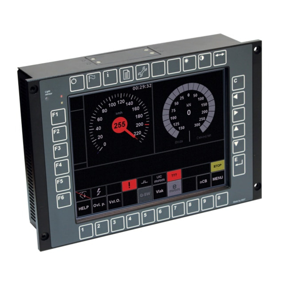
AWBDB0LA10F2GA 1. Introduction AWBDB0LA10F2GA is a PC platform panel computer. AWBDB0LA10F2GA series computer is designed for using in rolling stock. In following text, the device will be referred to only as ‘computer’. Computer AWBDB0LA10F2GA contains the Master processor module with... -
Page 7: Technical Parameters
AWBDB0LA10F2GA 2. Technical parameters Module MSC Q7-BT-15-20B2I ® Atom™ E3815, Single core, 1.6 GHz Intel 2 GB, DDR3L SDRAM FLASH memory 4 GB SATA SLC *) RTC backup Lithium battery BR2477, Panasonic Battery lifetime 5 years Note *) Memory is the fixed part of the module. - Page 8 AWBDB0LA10F2GA Quantity Operation indication Galvanic isolation Data transmission rate 12 Mbps / 480 Mbps Connection point M12 5-pin A-Code Recommended cabling Shielded USB cable Maximum cable length Note *) USB only for service usage. RS485 Quantity Operation indication Galvanic isolation Dielectric strength...
- Page 9 AWBDB0LA10F2GA Galvanic isolation Recommended cabling Coaxial cable 50 Ω Maximum cable length 5.5 m 2× RSMA jack (external thread) Connection points Power supply Nominal power supply voltage 24 V to 36 V DC Power supply voltage range 16.8 V to 50.4 V DC Power consumption *) Max.
- Page 10 AWBDB0LA10F2GA -30 °C to 70 °C Environmental Operating temperature range -30 °C to 70 °C conditions Storage temperature range Maximum ambient humidity < 95 % not condensing Note Device is functional within the whole range of operating temperatures immediately after switching on.
-
Page 11: Dimensions
AB12345 HW REV MAC X11: xx-xx-xx-xx-xx-xx AUX FW: APP x.xx / LDR x.xx POWER: 16.8 to 50.4 V DC / 1.5 A WEIGHT: x.xx kg TEST: OK-VS HiPot: HiPot - OK DATE: xx.xx.xxxx Fig. 1 - AWBDB0LA10F2GA dimensions 11/42 awbdb0la10f2ga_g_en_100... -
Page 12: Recommended Drawing Symbol
2.2. Recommended drawing symbol Following drawing symbol recommended panel computer AWBDB0LA10F2GA. AWBDB0LA10F2GA ETH1 ETH2 X1 / PWR D-SUB DE-9 RS485 type A D-SUB DE-9 screw M4 D-SUB DE-9 RSMA WiFi RSMA WiFi Fig. 2 - AWBDB0LA10F2GA drawing symbol awbdb0la10f2ga_g_en_100 12/42... -
Page 13: Block Diagram
WiFi driver module module Master CPU CPLD module 1.91GHz 4GB RAM PCIe LVDS Touchscreen Buzzer Auxiliary CPU Power Temperature sensor supplies LED, light sensor, keyboard PCIe to ETH CFast 4GB ETH1 ETH2 Fig. 3 - AWBDB0LA10F2GA block diagram 13/42 awbdb0la10f2ga_g_en_100... -
Page 14: Labelling
AWBDB0LA10F2GA 3. Labelling Type identification plate is placed on the back side of the AWBDB0LA10F2GA computer. For exact location of labels see Fig. 4 - Labelling of AWBDB0LA10F2GA computer. AWBDB0LA10F2GA TYPE AB12345 HW REV MAC X11: xx-xx-xx-xx-xx-xx AUX FW: APP x.xx / LDR x.xx POWER: 16.8 to 50.4 V DC / 1.5 A... -
Page 15: Manufacturer Type Plate
AWBDB0LA10F2GA 3.1. Manufacturer type plate Type identification plate is placed on the back side of the computer. Identification plate’s information is summarized in the table below, for example of filled manufacturer type plate see Fig. 5 - Example of manufacturer’s type plate. -
Page 16: Conformity Assessment
AWBDB0LA10F2GA 4. Conformity assessment The equipment meets the requirements of NV117/2016 Czech governmental decree. The compliance assessment with NV117/2016 has been performed in accordance with harmonized standard EN 50121-3-2:2016. Tested in accordance Type of test Classification with standard EN 55016-2-1:2014... -
Page 17: Other Tests
AWBDB0LA10F2GA 4.1. Other tests This product was assessed and approved for use in railway applications according to standards: Tested in accordance Type of test Classification with standard Railway applications – Electronic EN 50155:2007 Complies equipment used on rolling stock Railway applications – Electromagnetic... -
Page 18: Power Supply
AWBDB0LA10F2GA 5. Power supply Computer AWBDB0LA10F2GA must be powered from DC power supply only. Power supply voltage is connected to a PWR connector, terminals Vcc and GND. Terminal SB is used for computer turning on and off, terminal PE for connecting a computer chassis. -
Page 19: Power Supply Connector Pinout
AWBDB0LA10F2GA 5.1. Power supply connector pinout AWBDB0LA10F2GA computer is equipped with M12 connector labelled as PWR. It is used as a power supply connector. Note Matching counterpart is NOT contained in package. Signal Description connector Power supply pinout Computer chassis... - Page 20 AWBDB0LA10F2GA HW state SW state toff1 Fig. 7 - Correct start up / shut down Safe To prevent the data damage, the computer must be shut-down only via SB shutdown terminal. First, it is necessary to disconnect the supply voltage from SB terminal, which initiates correct termination of application and operating system.
- Page 21 AWBDB0LA10F2GA Fig. 9 - Correct start up / shut down Shutdown This state can cause corruption of data in the FLASH memory. It can occur if supply voltage is disconnected concurrently from both SB and Vcc terminals or, if shut down by Auxiliary CPU is activated before correct terminating the operating system.
- Page 22 AWBDB0LA10F2GA Fig. 11 - Incorrect switch off awbdb0la10f2ga_g_en_100 22/42...
-
Page 23: Internal Processor Modules
AWBDB0LA10F2GA 6. Internal processor modules 6.1. Master processor module Computer AWBDB0LA10F2GA contains as Master CPU an Intel Atom processor. ® Atom™ E3845 Quad-core processor. Core The core is based on Intel For more details see the MSC Q7-BT module datasheet on manufacturer's website (see the Related documentation section above). -
Page 24: Communication Lines And Peripherals
▪ Light sensor and LED indicators ▪ RTC battery backup 7.1. Ethernet The 10/100 Mbps Ethernet interface allows connecting of AWBDB0LA10F2GA computer to LAN network. Panel computer AWBDB0LA10F2GA is equipped with one Ethernet interface with M12-4pin Harting push-pull connector. TYPE... -
Page 25: Usb
Data reception, signal + Data transmission, signal - Data reception, signal - 7.2. USB Computer AWBDB0LA10F2GA contains 1 line of USB host type. USB connector is located on the rear panel of AWBDB0LA10F2GA computer. TYPE AWBDB0LA10F2GA AB12345 HW REV MAC X11:... -
Page 26: Rs485
AWBDB0LA10F2GA 7.3. RS485 Panel computers AWBDB0LA10F2GA series contain one RS485 interface. Line is galvanically isolated from other electronics. Line termination must be solved externally in cabling. For detail information about using RS485 line see the Related documentation – AP0016 – Principles of using RS485 interface. -
Page 27: Mvb
AWBDB0LA10F2GA 7.4. MVB Panel computer AWBDB0LA10F2GA contains a MVB communication line module RM-MVB10/12 manufactured by AMiT. Detail information about module is available at AMiT web site (see Related documentation). TYPE AWBDB0LA10F2GA AB12345 HW REV MAC X11: xx-xx-xx-xx-xx-xx AUX FW: APP x.xx / LDR x.xx POWER: 16.8 to 50.4 V DC / 1.5 A... -
Page 28: Gps
AWBDB0LA10F2GA 7.5. GPS Panel computer AWBDB0LA10F2GA contains a GPS module. Detail information about module is available at manufacture’s web site (see Related documentation). TYPE AWBDB0LA10F2GA AB12345 HW REV MAC X11: xx-xx-xx-xx-xx-xx AUX FW: APP x.xx / LDR x.xx POWER: 16.8 to 50.4 V DC / 1.5 A WEIGHT: x.xx kg... -
Page 29: Wifi
AWBDB0LA10F2GA 7.6. WiFi Panel computer AWBDB0LA10F2GA contains a WiFi module. The WiFi inter- face has two RSMA connectors for antennae. WiFi interface complies with fami- ly of standards IEEE 802.11 type a, b, g, n and ac 2.4 GHz and 5 GHz. -
Page 30: Circumferential Keyboard
Auxiliary CPU. Alternatively, the lighting sensor can be used for automatic control of panel keyboard backlight or for brightness control of LCD display backlight. LED indicators on panel serve for indication of AWBDB0LA10F2GA computer’s current status. awbdb0la10f2ga_g_en_100 30/42... - Page 31 AWBDB0LA10F2GA LED colour State indicated Indication Yellow Device is ON. Light Device internal temperature reached dangerous Flashing temperature. Device internal temperature is out of range Light -40 °C to 97 °C. Both LEDs can be toggled from status mode to user mode by Auxiliary processor commands;...
-
Page 32: Rtc Battery Backup
AWBDB0LA10F2GA 7.10. RTC battery backup AWBDB0LA10F2GA computer is equipped with battery for RTC backup, including the backup battery module holder for easy replacement. Battery module is placed under the service cover. If the RTC is not used, then backup battery replacement can be omitted. -
Page 33: Mounting
8. Mounting 8.1. Mounting instructions Panel computer AWBDB0LA10F2GA can be mounted in any position. To ensure proper cooling and access to the terminal we recommend to keep a free space of minimum 70 mm sidewise and 100 mm from rear side to surrounding equipment. - Page 34 AWBDB0LA10F2GA Section A-A - Hole detail: Fig. 22 - Mounting hole detail +1,0 -0,0 Fig. 23 - Suggested mounting opening awbdb0la10f2ga_g_en_100 34/42...
-
Page 35: Installation Rules
AWBDB0LA10F2GA 8.3. Installation rules The PE terminal of the power supply connector must be connected with a local installation grounding terminal. Although power connector contains PE terminal, for best connection we strongly recommend to use grounding screw near to X1. -
Page 36: Ordering Information, Bom
Following accessories can be ordered: Part ID Part description Quantity 21010000003 M12 sealing cap 43-00421 Power supply connector counterpart CFAST 4GB/I CFast card 4 GB *) Note *) For more information about storage sizes please contact technical support at email address support@amit.cz. awbdb0la10f2ga_g_en_100 36/42... -
Page 37: Packaging
AWBDB0LA10F2GA 10. Packaging Front panel Display area including front panel is protected by plastic foil against scratches protection and dirt. This foil is recommended to stay on the device during mounting to the vehicle and must be removed before using the device. -
Page 38: Storage
AWBDB0LA10F2GA 11. Storage To prevent any damage to the device please keep the following rules. Packed The computer in the original box must be stored only under environmental computer conditions defined in technical parameters. The device must be kept away from water, oil or any other liquid which can damage the packing. -
Page 39: Maintenance
AWBDB0LA10F2GA 12. Maintenance Warning Maintenance mentioned below can be performed only by manufacturer or authorized service. 12.1. Backup battery replacement Backup The backup battery lifetime is limited. Its replacement is necessary at least eve- battery ry five years. If special panel computer usage conditions are complied with, the service interval can be prolonged according to chart on Fig. - Page 40 SP_MB247720 Fig. 27 - Battery module replacement For correct function of computer AWBDB0LA10F2GA battery module must be screwed and thread-locked. As a thread-lock please use LOCTITE 222. After all of operation above, service cover MD AW/A put back and screw 6× flat head TORX T10 screw.
-
Page 41: Cleaning
AWBDB0LA10F2GA 12.2. Cleaning According to cleanliness of the environment, where the computer is installed, it is necessary to remove dust and dirt from the panel computer. Cleaning intervals have to be planned by the vehicle designer. According to the dust and dirt contamination level, there are cleaning ways as... -
Page 42: Waste Disposal
AWBDB0LA10F2GA 13. Waste disposal Electronics The disposal of electronic equipment is subject to the regulations on handling disposal electrical waste. The equipment must not be disposed of in common public waste. It must be delivered to places specified for that purpose and recycled.
Need help?
Do you have a question about the AWBDB0LA10F2GA and is the answer not in the manual?
Questions and answers