Table of Contents
Advertisement
Available languages
Available languages
Quick Links
CTRL-HS
Run
10 %
15.5
rpm
Manuale Istruzioni
2
I
Instruction Manual
15
EN
Sede operativa: via Mario Calderara 39/41, 25018 Montichiari (Bs) - Sede legale: via Corsica 10, 25125 Brescia
C.F. e P.IVA/VAT 03369930981 - REA BS-528635 - Tel: +39 030 674681 - Fax: +39 030 6872149
www.aerauliqa.com - info@aerauliqa.it
Ci riserviamo il diritto di modificare/apportare migliorie ai prodotti e/o alle istruzioni di questo manuale in qualsiasi momento e senza preavviso.
We reserve the right to modify/make improvements to products and/or this instruction manual at any time and without prior notice.
Advertisement
Table of Contents

Summary of Contents for aerauliqa CTRL-HS
- Page 1 C.F. e P.IVA/VAT 03369930981 - REA BS-528635 - Tel: +39 030 674681 - Fax: +39 030 6872149 www.aerauliqa.com - info@aerauliqa.it Ci riserviamo il diritto di modificare/apportare migliorie ai prodotti e/o alle istruzioni di questo manuale in qualsiasi momento e senza preavviso.
-
Page 2: Table Of Contents
• Si raccomanda che ciascun ventilatore abbia un interruttore di alimentazione indipendente in quanto l’assegnazione dell’indirizzo Modbus al ventilatore deve avvenire quando un solo ventilatore è presente sulla rete Modbus. 2.INSTALLAZIONE Fare riferimento al manuale fornito nell’imballo del pannello di controllo oppure consultare il sito www.aerauliqa.it 3.COLLEGAMENTO ELETTRICO Fare riferimento al manuale fornito nell’imballo del pannello di controllo oppure consultare il sito www.aerauliqa.it 3.1 COLLEGAMENETO MODBUS DEI VENTILATORI (DAISY CHAIN) • Utilizzare cavo twisted-pair... - Page 3 Se si desidera collegare al comando più ventilatori (max 4 unità), il collegamento da eseguire deve avere un inizio (comando) e una fine (ultimo ventilatore), come da immagine seguente: CTRL-HS CTRL-HS Collegamento T Fig. 1 Se i ventilatori non vengono collegati come da Fig. 1, potrebbe verificarsi un degrado del segnale di comunicazione e la rete potrebbe non funzionare correttamente. Attenzione: ciascun ventilatore deve avere un proprio indirizzo Modbus univoco.
- Page 4 0,6m (2ft). Se fosse necessario lasciare disponibile del cavo per un eventuale riposizionamento futuro del ventilatore, tirare il cavo fino al soffitto e riportarlo verso il basso (a forma di ferro di cavallo). EVITARE DI PIEGARE IL CAVO ECCESSIVAMENTE TAGLIARE IL CAVO IN ECCESSO CTRL-HS Fig. 3...
-
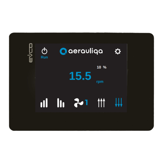
Page 5: Funzionalità
4.FUNZIONALITÀ 4.1 HOME PAGE Alarm 10 % 15.5 Modbus Tasto Descrizione Selezione modalità “Run” (ventilatore in funzione) oppure “Stop” (ventilatore fermo) Accesso alla schermata Configurazione del ventilatore (paragrafo 4.5) Selezione direzione flusso d’aria (ove disponibile): toccando i tasti si può variare la direzione del flusso. L’icona selezionata diventa blu dopo alcuni secondi. Selezione ventilatore: toccando l’icona si seleziona il numero del ventilatore Regolazione velocità: toccando i simboli oppure si aumenta o diminuisce la velocità... -
Page 6: Mpostazione Lingua E Numero Ventilatori Del Sistema
4.2 IMPOSTAZIONE LINGUA E NUMERO VENTILATORI DEL SISTEMA Quando alimentato per la prima volta, il CTRL-HS mostra la seguente schermata: Italiano Lingua: Modifica Ventilatori: Modifica Tasto Descrizione Lingua Selezione lingua (inglese o italiano) Modifica Ventilatori Impostazione numero ventilatori del sistema fino a massimo 4 unità Modifica Consenso per accedere alla schermata successiva Non è possibile accedere alla schermata successiva se non è stato impostato il numero di ventilatori (da 1 a 4) . Toccando il tasto Ok si accede alla seguente schermata: Numero di ventilatori: Prosegui... -
Page 7: Impostazione Indirizzi Modbus
4.3 IMPOSTAZIONE INDIRIZZI MODBUS Imposta indirizzo #1 Imposta indirizzo #2 Disponibile Disponibile Imposta indirizzo #3 Imposta indirizzo #4 Disponibile Non Disponibile ATTENZIONE Assicurarsi che sia collegato alla rete Modbus solo il ventilatore selezionato Tasto Descrizione Ritorno alla schermata precedente Ritorno alla schermata Home page Imposta indirizzo 1 Impostazione indirizzo Modbus ventilatore numero 1 Imposta... -
Page 8: Identificazione Allarmi
Se si seleziona un ventilatore con indirizzo Modbus non disponibile, sul display appare la seguente schermata: Questo indirizzo non è disponibile Tasto Descrizione Ritorno alla schermata precedente Ritorno alla schermata precedente 4.4 IDENTIFICAZIONE ALLARMI Agendo sul tasto della HOME PAGE, si accede alla seguente schermata: Alarm Allarmi Allarme1: Allarme2: Descrizione: Sincro motore persa Modbus Tasto Descrizione... - Page 9 Codici di allarme/Stato del LED sul corpo motore/Risoluzione Problemi LAMPEGGI LED VALORE VALORE (durata del DESCRIZIONE ALLARME ALLARME ALLARME RISOLUZIONE DEI PROBLEMI singolo POSSIBILI CAUSE lampeggio, ca.) 1 Lamp./2s Nessun errore (1s) 1 Lamp./s Errore di memoria – parametri motore persi Contattare il produttore/supporto tecnico. (0.5s) 2 Lamp./s Corto circuito – elettronica di potenza Scheda danneggiata –...
- Page 10 Toccando il tasto della HOME PAGE si accede alla seguente schermata: Modbus Comunicazione Modbus con indirizzo 1: Errore! In caso di errore verificare i collegamenti di comunicazione e alimentazione e l’attribuzione dell’indirizzo Modbus Tasto Descrizione Ritorno alla schermata precedente Ritorno alla schermata Home page Selezione del numero del ventilatore a cui la schermata fa riferimento Sul display appare l’indicazione “Errore!”...
-
Page 11: Configurazione
4.5 CONFIGURAZIONE Numero di Indirizzi Allarmi ventilatori Modbus Info Modalità Velocità motore controllo Contatto Sistema avviamento Tasto Descrizione Ritorno alla schermata precedente Ritorno alla schermata Home page Selezione del numero del ventilatore a cui la schermata fa riferimento Numero di Impostazione numero ventilatori del sistema (paragrafo 4.2) ventilatori Indirizzi... -
Page 12: Impostazione Velocità
4.6 IMPOSTAZIONE VELOCITÀ 10rpm min. max. 50rpm Modbus Tasto Descrizione Ritorno alla schermata precedente Ritorno alla schermata Home page Selezione del numero del ventilatore a cui la schermata fa riferimento Alarm Modbus: il simbolo appare e lampeggia se uno dei ventilatori non riesce a comunicare sulla rete Modbus. Toccandolo si ha accesso alla schermata “Identificazione Allarmi”... -
Page 13: Informazione Relative Al Motore
Possibilità di scelta tra Modbus e Analogico. In modalità “Analogico” la velocità del ventilatore e la modalità Modifica “Run/Stop” non possono essere gestite tramite il CTRL-HS. Tutte le altre funzioni rimangono attive. Selezione del numero del ventilatore a cui la schermata fa riferimento Alarm Modbus: il simbolo appare e lampeggia se uno dei ventilatori non riesce a comunicare sulla rete Modbus. -
Page 14: Impostazioni Contatto Di Avviamento
4.9 IMPOSTAZIONE CONTATTO DI AVVIAMENTO Abilitazione controllo avviamento Stato attuale: Non Attivo Modifica ATTENZIONE Se attivo collegare pin7 a pin4 per avviare il motore Modbus Tasto Descrizione Ritorno alla schermata precedente Ritorno alla schermata Home page Abilitazione contatto di avviamento: se abilitato è necessario collegare il pin 7 al pin 4 del connettore di comando Modifica del motore per avviare la rotazione Selezione del numero del ventilatore a cui la schermata fa riferimento... - Page 15 - Wire each single fan separately; - The CTRL-HS can control up to 4 HVLS fans. • It is recommended that each fan has a dedicated power supply switch since the setting of the Modbus address to one fan must be carried out when only one fan is connected to the Modbus network. 2.INSTALLATION Refer to the manual supplied in the control panel packaging or consult the website www.aerauliqa.com 3.WIRING DIAGRAM Refer to the manual supplied in the control panel packaging or consult the website www.aerauliqa.com 3.1 MODBUS NETWORK INSTALLATION (DAISY CHAIN) • Use twisted pair cable type • Minimum 24AWG (0,5mm) cable cross section.
- Page 16 If more fans (up to 4) need to be connected to one controller, the connection must have one beginning (CTRL-HS) and one end (last fan) as shown in the below images: CTRL-HS CTRL-HS T junction Fig. 1 If the fans are not connected as per Fig.1, there will be a degradation of the communication signal and the fan network may not function correctly.
- Page 17 0,6m (2ft) of excess cable at each connection point. If a longer cable is needed for future relocation of the fan, run the cable up toward the ceiling and back down in a horseshoe shape. ALWAYS AVOID SHARP BENDS OF THE CABLE. TRIM EXCESS CABLE CTRL-HS Fig. 3...
- Page 18 4.OPERATION 4.1 HOME PAGE Alarm 10 % 15.5 Modbus Button Description Selection between “Run” mode (fan rotates) or “Stop” (fans does not rotate) Fan settings (paragraph 4.5) Selection of the air flow direction (if available): touching the icons you can change the flow direction. The selected icon turns blue after few seconds.
- Page 19 4.2 SETTING OF THE LANGUAGE AND OF THE NUMBER OF THE FANS OF THE NETWORK When the unit is powered on for the first time, the following screen is diplayed: English Language: Fans: Button Description Language Language selection (English or Italian) Fans Setting of the number of fans of the network up to 4 units Confirm and access to the next screen It is not possible to access the next screen without setting the number of fans of the network (from 1 to 4) .
- Page 20 4.3 SETTING OF THE MODBUS ADDRESS Set address #1 Set address #2 Available Available Set address #3 Set address #4 Available Unavailable WARNING Make sure that only the selected fan is connected to the Modbus network Button Description Back to the previous screen Back to the Home Page address #1 Setting of the Modbus address of fan #1 address #2 Setting of the Modbus address of fan #2 address #3 Setting of the Modbus address of fan #3...
- Page 21 If a fan with an unavailable Modbus address is selected, the following screen is displayed: This address is not available Button Description Back to the previous screen Back to the previous screen 4.4 ALARM IDENTIFICATION Touching the icon in the Home Page, the following screen is displayed: Alarm Alarms Alarm1:...
- Page 22 Alarm Codes / Motor LED Status / Troubleshooting LED BLINKS ALARM 1 ALARM 2 ALARM DESCRIPTION (single blink TROUBLESHOOTING VALUE VALUE POSSIBLE CAUSE approx. duration) 1 Blink/2s No error (1s) 1 Blink/s Memory error – motor parameters lost Contact manufacturer/technical support (0.5s) 2 Blink/s Short circuit – electronics power Board damaged –...
- Page 23 Touching the icon in the Home Page, the following screen is displayed: Modbus Modbus communication with address 1: Error! In case of error, check the communication, the power connections and the assignment of the Modbus address Button Description Back to the previous screen Back to the Home Page Selection of the fan number On the screen the wording “Error!” and the Modbus address of the faulty fan are displayed.
- Page 24 4.5 SETTING Number Modbus Alarm of fans addresses Motor Control Speed info mode System input Button Description Back to the previous screen Back to the Home Page Selection of the fan number Number of Setting of the number of fans of the network (paragraph 4.2) fans Modbus Setting of the Modbus addresses (paragraph 4.3)
- Page 25 4.6 SPEED SETTING 10rpm min. max. 50rpm Modbus Button Description Back to the previous screen Back to the Home Page Selection of the fan number Alarm Modbus: the symbol is displayed and blinks if one of the fans does not communicate on the Modbus network.
- Page 26 Back to the Home Page Setting between Modbus or Analogic. In Analogic mode the fan speed and the Run/Stop mode can not be set with the CTRL-HS. Any other functionality remains active Selection of the fan number Alarm Modbus: the symbol is displayed and blinks if one of the fans does not communicate on the Modbus network.
- Page 27 4.9 RUN INPUT SETTING Run input Current status: Not Active WARNING When Active connect pin7 to pin4 to start the motor Modbus Button Description Back to the previous screen Back to the Home Page Run Input contact activation: if active, pin #7 of the motor connector must be connected to pin #4 to start the Change rotation Selection of the fan number...
- Page 28 004997 - 00 - 1020...
Need help?
Do you have a question about the CTRL-HS and is the answer not in the manual?
Questions and answers