Table of Contents
Advertisement
1. Read all instructions.
2. Use heat press only for its intended use.
3. To reduce the risk of electric shock, do not immerse the heat press in water or
other liquids.
4. Never pull power cord to disconnect from outlet, instead grasp plug and pull to
disconnect.
5. Do not allow power cord to touch hot surfaces, allow heat press to cool completely
before storing.
6. Do not operate heat press with a damaged cord or if the equipment has been
dropped or damaged. To reduce the risk of electric shock, do not disassemble or
attempt to repair the heat press. Take it to a qualified service person for
examination and repair. Incorrect assembly or repair could increase the risk of fire,
electric shock, or injury to persons when the equipment is used.
7. This appliance is not intended to be used by persons (including children) with
reduced physical, sensory or mental capabilities, or lack of experience and
knowledge, unless they have been given supervision or instruction concerning
use of the appliance by a person responsible for their safety.
8. Close supervision is necessary for any heat press being used which can be sure
to keep children away from the equipment. Do not leave equipment unattended
while connected.
9. Burns can occur when touching hot metal parts.
10. To reduce the likelihood of circuit overload, do not operate other high voltage
equipment on the same circuit.
11. If an extension cord is necessary, then a 20-amp rated cord should be used.
Cords rated for less amperage may overheat. To arrange the cord in a correct way
so that it cannot be pulled or tripped over.
Operation Manual
(GS-105HS)
Safety Instructions
When using your heat press,
basic precautions should be followed,
including the following:
1
Advertisement
Table of Contents

Related Manuals for Galaxy GS-105HS

Summary of Contents for Galaxy GS-105HS
- Page 1 Operation Manual (GS-105HS) Safety Instructions When using your heat press, basic precautions should be followed, including the following: 1. Read all instructions. 2. Use heat press only for its intended use. 3. To reduce the risk of electric shock, do not immerse the heat press in water or other liquids.
-
Page 2: Table Of Contents
Table of Contents Safety Instructions……………………….1 Technical Parameters……………………3 Machine View…………………………….4 Control Panel Guide……………………...5 Operating Instructions……………………6-10 ⚫ Assemble the Control Box……………………………………………6 ⚫ Connecting the System……………………………………………..7 ⚫ Ramspin system (Auto& Manual switch) …………………………...7 ⚫ Turning the System On…………………………………….…………8 ⚫ Adjusting the Temperature…………………………………………...8 ⚫ Adjusting the Time…………………………………………………..8 ⚫... -
Page 3: Technical Parameters
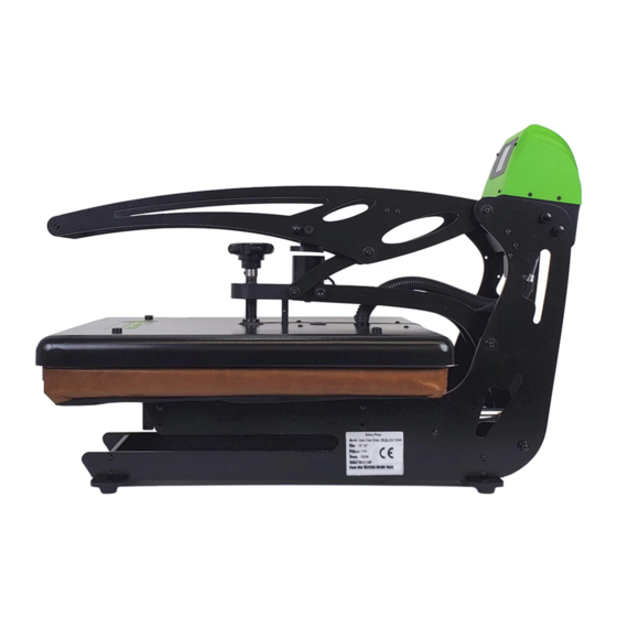
Technical Parameters (GS-105HS) Model: GS-105HS-1620 Heater Size: 16’’×20’’ Pressure Display: Auto Open: Yes / Can also be setup as a Manual Operation Press Slide-out Lower Platen: Power(110volt) 1800W/16.4Amps Temperature Range: Max. 430℉/ 221℃ Heating Up Time(180℃) 20 minutes Time Range:... -
Page 5: Control Panel Guide
Control Panel Guide Operation Instructions... -
Page 6: Assemble The Control Box
Assemble the Control Box 1. ASSEMBLE THE CONTROL BOX 1.1 Take out control box inside of the 1.2 Fasten the control box onto the packing carton, then place the control machine with 4 screws tightly. (figure box on top of the machine in the right 1.2) position. -
Page 7: Connecting The System
Connecting the System 2. CONNECT THE POWER CORD 2.1 Connect the power cord into a properly grounded electrical outlet with a sufficient amperage rating. ⚫ VOLTAGE 110 Volt – The GS-105(HS) requires a full 20-amp grounded circuit for 110-volt operation. ⚫... -
Page 8: Adjusting The Temperature
Turn on the System 3. Switch the System On Adjusting the Temperature 4. ADJUST THE TEMPERATURE 4.1 Press “SET” button. “Set Temp” lights located in the display will illuminate. (figure 4.1) 4.2 Next, press the UP and DOWN Arrow to increase or decrease the figure to set the Temperature. -
Page 9: Adjusting The Time
Adjusting the Time 5. ADJUST THE TIME 5.1 Once you have set your target Temp., press the “SET” button again. “Set Time” lights located in the display will illuminate. (figure 5.1) 5.2 Next, press UP and DOWN Arrow to increase or decrease the figure to set the Time. -
Page 10: Adjusting The Pressure
Adjusting the Pressure 7.ADJUST THE PRESSURE 7.1 First, locate the LED Display on the Press. The Pressure Adjustment Knob is located in the center of the heat platen (See figure 7.1) 7.2 To adjust the Pressure, simply turn the Pressure Adjustment Knob to the right or clockwise to increase the Pressure and to the left or counterclockwise to decrease the Pressure. -
Page 11: Switch Between F/C
Switch Between Fahrenheit and Celsius 9.Switch Between F/C 9.1 Press the UP Arrow and “SET” button together and hold for 3 seconds to switch between Fahrenheit and Celsius. F/C indicator in display will show the result. (fig.9.1) Temperature Calibration 10.Temperature Calibration 10.1 Press the DOWN Arrow and “SET”... - Page 12 Exploded Views Part Name Part No. Qty. Display overlay 1600549 Control box top 1200446 Circuit breaker 18A 1800349 On/off switch 1800346 Emergency stop button 1200579 socket 1800344 Triac 1800586 Cooing sheet 1300672 Terminal Block 1800345 Circuit Board 1800353 Magnet switch 1801814 Magnet 1800609...
- Page 13 5 phase aviation plug (Female) with wires welded 1800955 2 phase aviation plug (Female)with wires welded 1800962 Machine handle J.03.05.0568 Machine arm 1200409 Washer 20-13-15 2000296 Lift links 1200139 Machine body 1200397 Supporting block 1200043 Rubber foot 1800317 Machine foot 1200649 Stud 10-72.5 GC1-21B 1200051...
- Page 14 Sliding System Part Name Part No. Qty. Cooper bush 1200075 Sliding Lower Platen Base 1200426 Supporting Block 1200052 Bearing block 1200648 Plated bar fixed board 1200044 Plated bar 1701037 O shape washer 1200309...
- Page 15 “RAMLOCK” System Part Name Part No. Qty. Ramlock base 1200958 Ramlock locking sheet 1200960 Ramlock locking set (male) 1200961 Ramlock locking screw 1900959 Ramlock handle 1200956 Ramlock locking set (female) 1200957 Optional Platens (*Sold Separately) Part Name (SKU) Size LTPPLATENSETRAM-0404 4in x 4in LTPPLATENSETRAM-0610 6in x 10in...
-
Page 16: Electrical Schematic
Electrical Schematic...
Need help?
Do you have a question about the GS-105HS and is the answer not in the manual?
Questions and answers