
Summary of Contents for Adnacom AUS324
-
Page 1: User's Guide
Adnacom Inc. 200 - 5050 Kingsway Burnaby, BC V5H 4H2, Canada https://adnacom.com/ Adnacom AUS324 USB 3.2 Gen 2 Extender with 4 USB Ports User’s Guide... -
Page 2: Table Of Contents
AUS324 User’s Guide Rev. 1.0 Contents User’s Guide ......................................1 Terminology ....................................4 Applicable and Reference Documents ..........................5 Reference Documents ..............................5 Applicable Documents ..............................5 System Description ................................. 6 Overview ....................................6 Recommended Transceivers and Cables ......................... 7 3.2.1... - Page 3 AUS324 User’s Guide Rev. 1.0 USB324 Drawings ................................19 USB324 Connectors ............................... 19 USB324 LEDs Description ............................20 USB324 DIP Switch Description ..........................20 USB324 Mechanical ............................... 21 9.5.1 USB324 Dimensions ............................21 9.5.2 Wall Mounting Brackets ............................. 22 Web Interface ..................................23 10.1 Overview .....................................
-
Page 4: Terminology
AUS324 User’s Guide Rev. 1.0 1 Terminology Table 1-1. Common Terms Used in the User’s Guide. Term Description Active optical cable A PCIe link with “N” lanes Electromagnetic Interference Electrostatic Discharge Gbps Gigabit per second Gb/s Gigabit per second PCIe Gen 3... -
Page 5: Applicable And Reference Documents
AUS324 User’s Guide Rev. 1.0 2 Applicable and Reference Documents Reference Documents RD-1: H14 Datasheet. Adnacom Inc., https://adnacom.com. RD-2: H18 Datasheet. Adnacom Inc., https://adnacom.com. RD-3: AUS324 Datasheet. Adnacom Inc., https://adnacom.com. Applicable Documents AD-1: Universal Serial Bus 3.2 Specification, Revision 1.0. USB-IF, https://usb.org/. -
Page 6: System Description
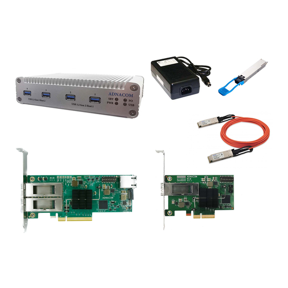
3 System Description Overview The Adnacom AUS324 is a USB 3.2 Gen 2 extender that supports USB 3.2 Gen 2 (10 Gb/s) and Gen 1 (5 Gb/s), 2.0, and 1.1 devices. The system consists of an Adnacom PCIe host adapter and a USB324 remote unit connected by a fiber optic cable. -
Page 7: Recommended Transceivers And Cables
3.2.2 Optical Transceivers The AUS324 can operate with standard multimode and single mode QSFP transceivers. The transceivers should consume less than 1.5 W to keep their temperature within recommended operating conditions. If transceivers consume more than 1.5 W, heatsinks should be installed on the QSFP cages. -
Page 8: System Operation
AUS324 User’s Guide Rev. 1.0 4 System Operation USB Bandwidth Allocation To achieve the maximum USB data rate, the required device bandwidth must be allocated between USB ports and host controllers, as described in this section. The USB324 unit contains two independent ASM3142 USB host controllers, as shown in Figure 3-1. -
Page 9: System Installation
Therefore, disabling all power management features on the computer is recommended. The step-by-step instructions for Windows 7, 8, and 10 can be found at https://adnacom.com/aus324. For other OSs, please consult your OS documentation, and if you need additional assistance, please contact the OS vendor. -
Page 10: Connecting Usb Devices
AUS324 User’s Guide Rev. 1.0 included in the Windows 10 and Linux operating systems. If the drivers are not installed when the system is powered for the first time, the computer requires one or two restarts. Connecting USB Devices •... -
Page 11: System Functionality Verification
AUS324 User’s Guide Rev. 1.0 6 System Functionality Verification To verify a successful installation, use the Device Manager. In the Device Manager, click on the View menu and select View Devices by Connection. Figure 6-1. Device Manager. Adnacom Inc. 11 of 34... - Page 12 PCI bridge.” Under one of the lines, you should see three PCI-to-PCI bridges and two AsMedia USB 3.1 Host Controllers, as shown in Figure 6-2. Figure 6-2. AUS324 System with H14 View in Device Manager. Adnacom Inc. 12 of 34...
-
Page 13: H14 Pcie Host Adapter
AUS324 User’s Guide Rev. 1.0 7 H14 PCIe Host Adapter H14 Drawing Figure 7-1. H14 Drawing. H14 Cable Interface Table 7-1. H14 PCIe Cable Interface. Number of Port Port Width PCIe Lanes QSFP QSFP PCIe Ports Number TX/RX 0–3 1–4 0–1... -
Page 14: H14 S1 Dip Switch Description
AUS324 User’s Guide Rev. 1.0 H14 S1 DIP Switch Description Table 7-2. H14 DIP Switch. Switch Description Default Cable Interface Configuration S1.1 Configuration 1 port x4 2 ports x2 Note: The USB324 works with the S1.1=ON configuration. Reserved Gen 2 Cable Interface OFF –... - Page 15 AUS324 User’s Guide Rev. 1.0 Table 7-4. PCIe Link Status. PCIe Link LED Description Link is Down Blinking, 0.5 sec ON, 0.5 sec OFF (1 Hz) Link is Up, 2.5.0 GT/s Blinking, 0.25 sec ON, 0.25 sec OFF (2 Hz) Link is Up, 5.0 GT/s...
-
Page 16: H18 Pcie Host Adapter
AUS324 User’s Guide Rev. 1.0 8 H18 PCIe Host Adapter H18 Drawing Figure 8-1. H18 Drawing. H18 Cable Interface Table 8-1. H18 PCIe Cable Interface. Number of Port Port Width PCIe Lanes QSFP QSFP PCIe Ports Number TX/RX H18 S1 DIP Switch Description Table 8-2. -
Page 17: H18 Leds Description
AUS324 User’s Guide Rev. 1.0 Switch Description Default Gen 2 Cable Interface OFF – Gen 3 ON – Gen 2. Set for Gen 2 ports or to limit the cable interface speed Optical Reset OFF – Disabled ON – Enabled. The lasers are turned OFF during the computer reset. -
Page 18: H18 Connectors Description
AUS324 User’s Guide Rev. 1.0 Color Description Blue Remote Link 2 Status: One port configuration: The status is the same as the Remote Link 1 status if QSFP 2 is connected to the remote device Two ports configuration: Port 2 link status described in Table 7-4... -
Page 19: Usb324 Remote Unit
AUS324 User’s Guide Rev. 1.0 9 USB324 Remote Unit USB324 Drawings Figure 9-1. USB324 Front Panel. Figure 9-2. USB324 Rear Panel. USB324 Connectors Table 9-1. USB324 Front Panel. Description Port 1 of USB Host Controller 1 Port 2 of USB Host Controller 1... -
Page 20: Usb324 Leds Description
AUS324 User’s Guide Rev. 1.0 USB324 LEDs Description Table 9-3. USB324 LEDs. Color Description Standby Status: ON – Standby mode OFF – USB324 is ON, or the power supply is OFF. Green Power Status: ON – USB324 is ON. OFF – USB324 is OFF. -
Page 21: Usb324 Mechanical
AUS324 User’s Guide Rev. 1.0 USB324 Mechanical 9.5.1 USB324 Dimensions All dimensions are specified in mm. Figure 9-3. USB324 Dimensions. Adnacom Inc. 21 of 34 https://adnacom.com/... -
Page 22: Wall Mounting Brackets
AUS324 User’s Guide Rev. 1.0 9.5.2 Wall Mounting Brackets Optional wall mounting brackets can be ordered separately. The bracket-kit drawing and its content are shown in Figure 9-4. Figure 9-4. USB324 Wall Mounting Kit. Figure 9-5. USB324 Dimensions with Brackets. -
Page 23: Web Interface
Network Configuration page shown in Figure 10-2. The user’s IP address can be static or assigned by a DHCP server. When the DHCP server assigns the IP address, the website is accessed using the programmed DHCP hostname: for instance, http://ADNACOM-H18. The DHCP name is not case- sensitive. - Page 24 AUS324 User’s Guide Rev. 1.0 Figure 10-2. IP Address Configuration. Adnacom Inc. 24 of 34 https://adnacom.com/...
-
Page 25: H18 Web Site Ip: 192.168.100.101
AUS324 User’s Guide Rev. 1.0 10.3 H18 Web Site IP: 192.168.100.101 10.3.1 Overview The website consists of 4 pages: Status, Network Configuration, Firmware Upgrade, and Help, as shown in Figure 10-3. Figure 10-3. H18 Web Site. 10.3.2 Status Page 10.3.2.1 Configuration Table 10-1. -
Page 26: Status
AUS324 User’s Guide Rev. 1.0 Field Description Serial Number The serial number of the board used in the PCIe switch configuration space and as the MAC address PCIe Switch PEX8718 – PCIe switch part number Table 10-2. DIP Switch. Field... - Page 27 AUS324 User’s Guide Rev. 1.0 Field Description Recovery The recovery state counter. The counter is used to evaluate the link quality. It should not count during the operation. A slow increment is acceptable. Rx Error The receiver error counter. The counter is used to evaluate the link quality. It should not change during the operation.
- Page 28 AUS324 User’s Guide Rev. 1.0 Table 10-10. QSFP Status. Field Description QSFP The QSFP number on the board Power The power supply type powering the QSFP State The QSFP state The transmitter status The receiver status LoS Counter The Loss of Signal counter from the last reset...
-
Page 29: Troubleshooting
5. Document the findings, actions, and outcomes. 11.2 System Context Diagram The AUS324 extension consists of the following components: a computer, a host adapter, a QSFP cable, a USB324 unit, and USB devices connected to the USB324. The AUS324 components and their interfaces are shown in Figure 11-1. -
Page 30: Review Operating And Installation Instructions
AUS324 User’s Guide Rev. 1.0 11.3.2 Review Operating and Installation Instructions The operation and installation instructions are provided in sections 4 and 5, respectively. If the system is installed correctly, remove the host adapter from the computer and install it step-by- step, as described in the following sections. -
Page 31: Verify Usb Devices
AUS324 User’s Guide Rev. 1.0 If the USB324 is visible in the Device Manager as described in section 6, continue to the next section. 11.3.7 Verify USB Devices Connect USB devices and verify that devices are detected and installed properly in the operating system. -
Page 32: Products Design Disclaimer
Rev. 1.0 12 Products Design Disclaimer The Adnacom products are designed according to USB and PCI Express specifications listed in their respective datasheets. Hence, they should work with any USB devices and drivers compliant with those USB and PCI Express specifications. Adnacom can only provide limited support with 13 Customer Support third-party USB device installations. -
Page 33: Customer Support
Rev. 1.0 13 Customer Support For the latest Customer Support information, please visit our website at https://adnacom.com/. When contacting us, please make sure to include all the information below and describe your problem in detail to help us understand your problem better. -
Page 34: Warranty
Customers’ right to recover damages caused by fault or negligence on the part of Adnacom is limited to the amount paid by the customer. Adnacom is not liable for damages resulting from loss of data, profits, use of products, or incidental or consequential damages, even if advised of the possibility thereof.
Need help?
Do you have a question about the AUS324 and is the answer not in the manual?
Questions and answers