Table of Contents
Advertisement
Quick Links
Advertisement
Table of Contents

Related Manuals for HTC CE8200


Summary of Contents for HTC CE8200
-
Page 2: Table Of Contents
CONTENT Ⅰ. Safety Rules and Precautions ..........2 Ⅱ. Brief Introduction ..............4 Ⅳ. Range and Accuracy ..............5 1.Ranges and Accuracy of Measurement ........5 VII. LCD Display ................9 Description of Special Symbols ..........10 VIII. Measuring Principle ............... 11 IX. -
Page 3: Ⅰ. Safety Rules And Precautions
Ⅰ. Safety Rules and Precautions clamp grounding Thank you for purchasing our company's resistance tester . Before using the instrument for the first time, in order to avoid possible electric shock or personal injury, please read and strictly observe the safety rules and be sure to: precautions listed in this manual In any case, use this instrument should pay special attention to... - Page 4 Do not withhold the trigger and do not clamp any wires when turning on the meter After the power is turned on normally, the "OL Ω" symbol is displayed, and the measured object can be clamped. Do not place and store the instrument for a long period of time under conditions of high temperature, humidity, condensation, and direct sunlight.
-
Page 5: Ⅱ. Brief Introduction
Because of the reason of this instrument, if it is dangerous to continue using it, it should be immediately stopped and sealed immediately, and it should be handled by a qualified organization. The " " safety warning sign in the instrument and manual must be operated strictly in accordance with the contents of this manual. -
Page 6: Ⅳ. Range And Accuracy
At the same time data storage and data upload functions III. Model differentiation Model Resistance Current Range Range CE8200 0-1000Ω Ⅳ. Range and Accuracy 1. Ranges and Accuracy of Measurement Mode Range Resolution Accuracy 0.010Ω-0.099Ω... - Page 7 Ⅴ. Technical Specifications Functions Ground resistance test, Loop resistance test Ambient Temperature 23℃±5℃,below 75%rh and Humidity DC 6V (4 AA alkaline dry batteries) Power Supply Range CE8200 Resistance:0.01-1000Ω Measure Method Mutual induction 0.001Ω Resistance Resolution Jaw Size 55mm×32mm Clock Function Have...
- Page 8 Automatic shut-down Turn off after 5 minutes Power Consumption 50mA Max Weight Meter:1180g (including battery) Working Temperature -10℃~40℃;below 80%rh and Humidity Storage Temperature -20℃~60℃;below 70%rh and Humidity Insulation Resistance Above 20MΩ (500V between circuit and case) Pressure resistance AC 3700V/rms(between circuit and case) <40A/m External Magnetic Field...
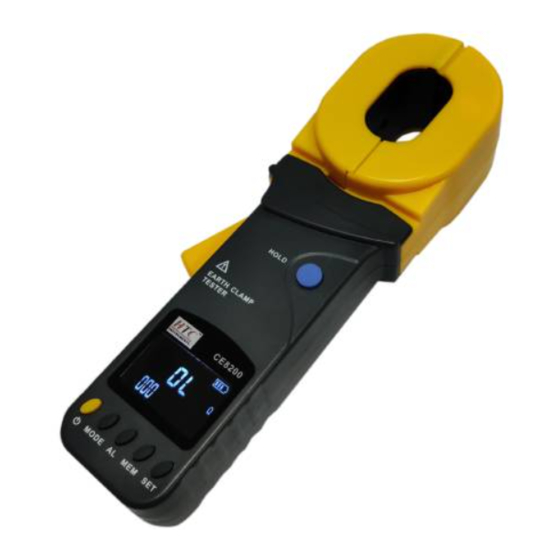
- Page 9 Ⅵ.Structure of Meter 1. Clamp Jaw 2. Trigger 3. LCD 4. POWER Key 5. MODE Key 6. AL Alarm Function Key 7. MEM Key 8. SET Key 9. HOLD Key 10.CALIBRATION LOOP:1Ω 11. CALIBRATION LOOP:10Ω...
-
Page 10: Lcd Display
VII. LCD Display (1). Jaw Open Symbol (2). Alarm Symbol (3). Symbol of Greater Than (4). DC AC Symbol (5). Symbol of data access (6). Symbol of data memory (7). Noise signal (8). Data lock symbol (9). Symbol of battery (10). -
Page 11: Description Of Special Symbols
Description of Special Symbols ⑴ . Symbol of an open jaw: As a jaw is in the open state, the symbol shows. At this point, trigger may be artificially pressed, or the jaws have been seriously polluted, and can no longer continue to measure. ⑵... -
Page 12: Measuring Principle
guaranteed. VIII. Measuring Principle The basic principle of the ground resistance measurement of the clamp-type grounding resistance meter is to measure the loop resistance. See below. The jaw section of the clamp meter consists of a voltage coil and a current coil. The voltage coil provides the excitation signal and induces a potential V on the circuit under test. -
Page 13: Battery Voltage Check
clamp any wire Boot complete, show “OL Ω”, then press the trigger, open jaws, clamp the measured wire Before booting up, the trigger should be pressed for a couple of times to ensure the jaws are well closed. Boot, must maintain clamp meter natural resting state, don’t flip Clamp, don’t be imposed outside force on the jaw, otherwise can not guarantee the accuracy of measurement... -
Page 14: Resistance Test
measurement. 3. Resistance Test When the user thinks that the grounded value does not conform to the normal, you can use a random calibration ring to check whether the clamp meter is normal. The check ring has two resistances of 1Ω and 10Ω. After the power-on self test is completed, the large middle digit shows “OLΩ”... -
Page 15: 4.Clock Settings
Resistance + clock mode: The circuit of the measured resistance exceeds the lower limit, The number of save groups is the current time is 12:08 4.Clock Settings After power on, long press the "SET" button (more than 3 seconds) to enter the clock setting mode. When the time data flashes, it is in the modified state. -
Page 16: Date Lock
6.Date Lock After the measurement is stable after power on, short press “HOLD” key to lock the current display data, save the data, and press “HOLD” key again to exit lock mode. As shown below: 7.Data Storage / Review / Delete When the measurement is completed after power on, short press "HOLD"... -
Page 17: Ⅹ. Battery Instructions
Ⅹ. Battery Instructions When the voltage drops to 5.2V, the battery symbol " " is displayed. Please replace the battery. Low battery voltage affects measurement accuracy. ⅩI. Field Application 1. Multi-Point Grounding System As for the multi-point grounding system (such as electricity transmission tower grounding... -
Page 18: Limited Point Grounding System
Although strictly on the theoretical grounding, because of the existence of so-called "mutual resistance”, R is not the usual parallel value in the sense of electrical engineering (slightly higher than its IEC parallel output value). But because a tower-grounding hemisphere was much smaller than the distance between the towers, and with a great number of locations after all, R is much smaller than R... - Page 19 .. .. .. ) 1 Where: R1、R2、……R are grounding resistances of N grounding bodies. 、R 、……R are the resistances measured with the Meter in the different grounding branches. It is nonlinear equations with N unknown numbers and N equations.
-
Page 20: Single-Point Grounding System
However, users need to pay attention to that: in response to the number of the grounding bodies mutually linked in your grounding system, it is necessary to measure the same number of the testing values for calculating of the program, not more or less. And the program would output the same number of grounding resistance values. - Page 21 As the resistance value measured by the Meter is the value of the series resistance from the testing line and two grounding resistances. Where: R is the resistance value measured with the Meter. is the resistance value of the testing line. Meter can measure out the resistance value by connecting the test lines with both ends.
- Page 22 Second, have R and R linked up, as shown in the following figure. Use the Meter to get the second reading R Third, have R and R linked up, as shown in the following figure. Use the Meter to get the third reading R In the above three steps, the reading measured in each step is the value of the two series grounding resistance.
-
Page 23: Ⅺi. Accessories
As the reference points, the grounding resistance values of the other two grounding bodies are: RB=R1-RA RC=R3-RA Ⅺ I. Accessories Earth Tester Battery 4 X AA alakaline battery Test Loop User’s Manual 1SET Carrying Case... - Page 24 HTC INSTRUMENTS www.htcinstrument.com...
Need help?
Do you have a question about the CE8200 and is the answer not in the manual?
Questions and answers