Advertisement
Quick Links
MOUNT THE BUTTON DEVICE
• Use device to mark installation location.
• Choose the best location and orientation to
make the push button easy to access by the user,
as well as to connect the network cable.
• Secure
device
using
appropriate for the installation surface.
•
Drywall: #8-32 steel screw x 1-5/8" min. length
fastened to a 75 lbs. rated drywall anchor, or
similar
•
Concrete: #8-32 steel screw x 5/8" min. length
fastened to a 8-32 concrete anchor with 9/16"
min. length, or similar
CONNECT TO THE NETWORK
• Connect a network cable (CAT 5 or better) to the
RJ-45 port (PoE/PoE+).
• Connect the other end of the network cable to
an LPS (Limited Power Source) PoE (Power over
Ethernet) network switch or PoE injector on a
network with a DHCP server.
ACCESS THE DEVICE
Use one of these ways to access the device:
• Enter the IP address assigned by the DHCP server
in your browser.
• Enter the
IPv6 link-local address in your browser,
formatted
http://[fe80::2246:f9ff:feXX:XXXX]
last 6 digits of MAC address).
• Double-click on the device in the IPClockWise
Endpoints list to open the web server interface.
Advanced Network Devices • 3820 Ventura Dr. Arlington Hts. IL 60004
mounting
hardware
as
(XX:XXXX =
tech@anetd.com
• 847-463-2237 •
(IPBTN) Installation
•
For third-party software application, consult
guide
for
access
configuration file).
CONFIGURE THE BUTTON
• Set up the button to trigger notifications, alerts,
or other signal (see next page).
• Consult
the
(available
on
www.anetd.com/portal/)
software guide for further instructions.
• Test before putting it into service.
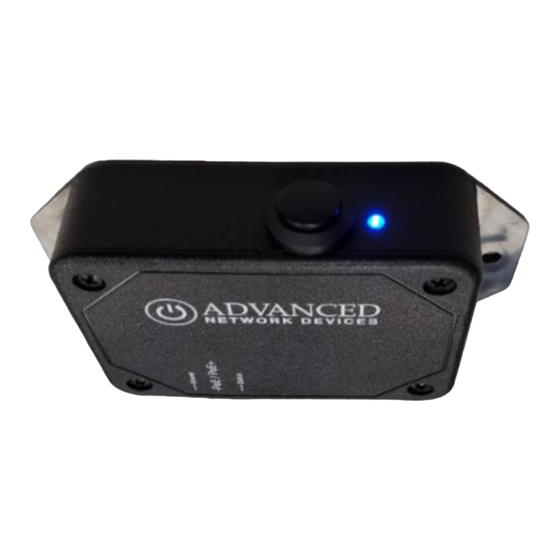
OPERATION
The front panel blue LED provides feedback on a
button push. The LED flashes upon the initial
button press. Once the device then connects to a
SIP phone or HTTP Callback server, the LED will
stop flashing and remain on solid for at least 5
seconds.
CONFIGURATION OPTIONS
The device ships with default settings:
SIP Mode
Push-to-Talk 1 Trigger Only
Activate GPIO 0 During Active Call
Send Activations Only
GPIO 0 Output Pulse Time
GPIO 0 Output Blink Period
Indicate GPO
Indicate Trying Action
Indicate Success Action
Configuration File Setup
<SIPConfig
SIP_mode="button"
push_to_talk_ip1_trigger_mode="1"
gpio0_when_active_call="1" />
<GPIO
pulse_ms_output_gpio0="5000"
www.anetd.com/
1
Smart IP Button
method
(often
IPClockWise
User
Manual
the
Customer
or
third-party
"Button"
"Yes"
"Yes"
"Yes"
"5000"
"500"
"0"
"Blink"
"Pulse"
uses
Portal
v2.2
Advertisement

Summary of Contents for ADVANCED Network Devices IPBTN
- Page 1 6 digits of MAC address). push_to_talk_ip1_trigger_mode="1" • Double-click on the device in the IPClockWise gpio0_when_active_call="1" /> Endpoints list to open the web server interface. <GPIO pulse_ms_output_gpio0="5000" Advanced Network Devices • 3820 Ventura Dr. Arlington Hts. IL 60004 tech@anetd.com • 847-463-2237 • www.anetd.com/ v2.2...
- Page 2 (registered or direct SIP call) to dial Legal Disclaimer: https://www.anetd.com/legal/ a different SIP extension when holding the button for a specified time or longer. Advanced Network Devices • 3820 Ventura Dr. Arlington Hts. IL 60004 tech@anetd.com • 847-463-2237 • www.anetd.com/ v2.2...