
Summary of Contents for Hummingbird HMSM2000CKIT
- Page 1 Installation and Operation Manual HMSM2000CKIT Silent Horn Elite System for Trucks HMSM2200CKIT Silent Horn Elite System for Diggers Version 1.3 – 30/11/2017...
-
Page 2: Table Of Contents
Fault Finding ............................18 Antenna Indicator ......................... 18 Display Error Messages ......................19 Parts and Accessories ..........................21 HMSM2000CKIT AND HMSM2200CKIT Main Components ..........21 HMSM2000CKIT AND HMSM2200CKIT ACCESSORIES ............22 HMSM1010CC WIRING LOOM ....................25 5.3.1 Wiring loom pinouts ..................... 25... -
Page 3: Hmsm2000C Truck Installation
HMSM2000C TRUCK INSTALLATION HMSM2000C TRUCK KIT The following photo details the content of the truck kit RAM mount Antenna Deutsch plug Antenna Display 2 x antenna mounting brackets Display loom Version 1.3 – 30/11/2017... -
Page 4: Display Buttons
DISPLAY BUTTONS Throughout this manual there will be references to the display buttons. These buttons are identified in the next photo. Down Menu Enter 1.3 TRUCK INSTALLATION 1.3.1 The display loom does not have the Deutsch connector for the antenna terminated, this is to either allow for cable to be lengthened or shortened depending where the antenna is located. - Page 5 1.3.2 Splice the red and black wires from the supplied four core into the trucks power line, it is a good idea to also place a 1A fuse in series whilst doing this. The other two pair cable on the supplied loom (red and blue) is to allow for an external buzzer/alarm to be fitted, if you are using one, do this now.
- Page 6 1.3.4 Power up the unit by plugging in both the connectors. On start up the following messages will be displayed When the system is powered up for the first time, the screen will display the following default ‘My ID’ setting of ‘0’...
- Page 7 1.3.6 Follow the next screen shots to enter the configuration menu Use the ‘up’ arrow and the ‘enter’ key to enter the default password of ‘12345’ If you need to change a number you have already confirmed, hold down the MENU key for 2 seconds to go back and edit the previous number. 1.3.9 If the entered password is correct, the configuration menu will be displayed.
-
Page 8: 1.4 Configuration Menu Options
1.4 CONFIGURATION MENU OPTIONS 1.4.1 The options below will be visible when the configuration menu is accessed, use the ‘down’ arrow to scroll through the options. Pressing the menu button at any time will save the settings and re-start the display. The following list details what each configuration option does: Timeslot: - Sets the mode, to make the display a Digger or Truck. - Page 9 Main Display Mode: - The display can be set to two modes: Detailed and Simple: Simple: Only the Machine ID and System status are displayed on the main screen. Detailed: The Machine ID, Satellites, Time/date, System Status and Tilt are displayed on the main screen.
- Page 10 1.4.2 (OPTIONAL) To finish the installation and setup of the truck silent horn is to give the unit an ID number that is assigned to the vehicle, in this example it is 25 The silent horn is now ready for use. Version 1.3 –...
-
Page 11: Hmsm2200C Digger Installation
HMSM2200C DIGGER INSTALLATION THE HMSM2200C DIGGER KIT 2.1.1 The digger kit installation is ostensibly the same as the truck installation except the IO module is introduced. The wiring and installation of the display and antenna is exactly the same as the truck Deutsch for IO Module... -
Page 12: Digger System Wiring Diagram
DIGGER SYSTEM WIRING DIAGRAM INTERFACE MODULE WIRING 2.3.1 The interface module has 4 sets of 12-pin Deutsch connectors, labelled A, C, D and B. Red - Power In Spare Power In1 Horn button switch + C3 Spare Power In2 Yellow - Communication B Relay 6 Relay 1 (Not used in this version) Relay 2 (Not used in this version) -
Page 13: Horn Button Switch
HORN BUTTON SWITCH: 2.4.1 The horn button switch’s contacts must be normally open. When the button is pressed, A3 (Horn button +) and A10 (Horn button –) will be shorted and this will create and display a horn blast in the cabin on the HMSM1010CC. The duration of this horn blast is set under the Configuration Menu –... -
Page 14: Setting The Digger Display
SETTING THE DIGGER DISPLAY 2.5.1 Enter the configuration menu as shown in the truck guide. The next sequence of photos will show how to configure the display as a ‘Digger’ The default settings for the configuration menu prior to setting as a digger. - Page 15 Notice when you set the display to ‘Digger’ that menu options only relevant to ‘Truck Mode’ become unavailable. The other options are now greyed out. Now set the ‘Machine’s ID’, in this example it is set to 5. Push ‘Enter’ to save.
- Page 16 When all options are set, push the menu button to restart the display and observe the start- up checking that there are no errors. Digger display ready to use Version 1.3 – 30/11/2017...
-
Page 17: Hmsm2000C Truck Pairing Menu
HMSM2000C TRUCK PAIRING MENU A HMSM2000 can be set to trigger to a specific digger by utilising the ‘PAIR’ feature. This function primarily exists when two diggers are operating within close proximity of one another and you require a truck to be operating in conjunction with its assigned digger. This is done by selecting PAIR to option on the display and will allow you to: 3.1.1 Select a digger that has previously been detected, or... -
Page 18: Fault Finding
FAULT FINDING ANTENNA INDICATOR 4.1.1 On the base of each antenna the is a LED that provides the status of the system. The LEDs different conditions are detailed in the following table. Colour Meaning Action Red flashing once The display is set as a Truck. Swap in a known working antenna, per second if OK, tag faulty antenna and return... -
Page 19: Display Error Messages
DISPLAY ERROR MESSAGES 4.2.1 The display will give an indication on the screen if there is a problem. These errors are This error will occur on power up in either ‘Digger’ or ‘Truck’ mode. There are no communications between the display and the antenna. - Page 20 SA: Smart antenna has stopped responding. Refer to section 1.3 to check the wiring. ID: Machine ID set to zero. Refer to section 1.4.1 to configure the Machine ID correctly. IO: The interface module has a problem. Check the power and communications wiring.
-
Page 21: Parts And Accessories
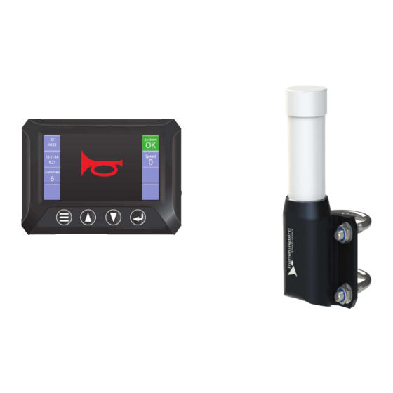
Note: If the System tile does not show OK, the system will not function correctly. If the horn button is pressed, ‘HORN CANNOT BE ACTIVATED’ will be displayed and a horn trigger will not be sent from the unit. PARTS AND ACCESSORIES HMSM2000CKIT AND HMSM2200CKIT MAIN COMPONENTS Smart Display Part Number: HMSM1010C Version 1.3 – 30/11/2017... -
Page 22: Hmsm2000Ckit And Hmsm2200Ckit Accessories
Smart Antenna Part Number: HMSM0001C IO Module Part Number: HMSM0010 HMSM2000CKIT AND HMSM2200CKIT ACCESSORIES 5.2.1 DEUTSCH ACCESSORIES Plug D Part Number: CON157 Version 1.3 – 30/11/2017... - Page 23 Plug A Part Number: CON154 Part Number: CON200 Part Number: CON074 HMSM0100 IO Module requires x 6 HMSM0001C Smart Antennae requires x 4 5.2.2 RAM ACCESSORIES Part Number: RAM-B-238U Version 1.3 – 30/11/2017...
- Page 24 Part Number: RAP-B-379U-252025 Part Number: RAM-B-201U 5.2.3 ANTENNA BRACKETS Part Number: ENC183 Two per antenna Version 1.3 – 30/11/2017...
-
Page 25: Hmsm1010Cc Wiring Loom
HMSM1010CC WIRING LOOM Part Number: CON015 x 2m Part Number: Con214 x 0.5m Part Number: CON234 5.3.1 W IRING LOOM PINOUTS CON234 plug view from the front Red wire CON015 Red wire CON214 Black wire CON015 & Blue wire CON214 Green wire CON015 Yellow wire CON015 Version 1.3 –... - Page 26 Technical Queries: Tel: 1300 155 541 E-mail: admin@hmbe.com.au Version 1.3 – 30/11/2017...
Need help?
Do you have a question about the HMSM2000CKIT and is the answer not in the manual?
Questions and answers