Advertisement
Quick Links
Piano Stool Hardware Kit
This kit provides the key hardware components to make a height-
adjustable piano stool. It consists of a seat base and threaded
shaft assembly and a steel nut that provide a total seat adjustment
of 6". The seat base and threaded shaft assembly is mounted to the
underside of a piano stool seat, and the 3" long by 1.245" outside
diameter nut is mounted in a hole drilled in a wooden base/cap.
The design of the hardware components is such that there will
always be at least 2" of engagement of the threaded shaft in the nut
to prevent the seat from being spun out of its base. The instructions
that follow provide dimensional guidelines so you can design a
stool that suits your needs.
Design Considerations and Assembly
If you are building a four-legged piano stool, the footprint
should be larger in diameter than the seat diameter to reduce the
possibility of the stool tipping over. A three-legged design would
require a larger footprint, since three legs are less stable than
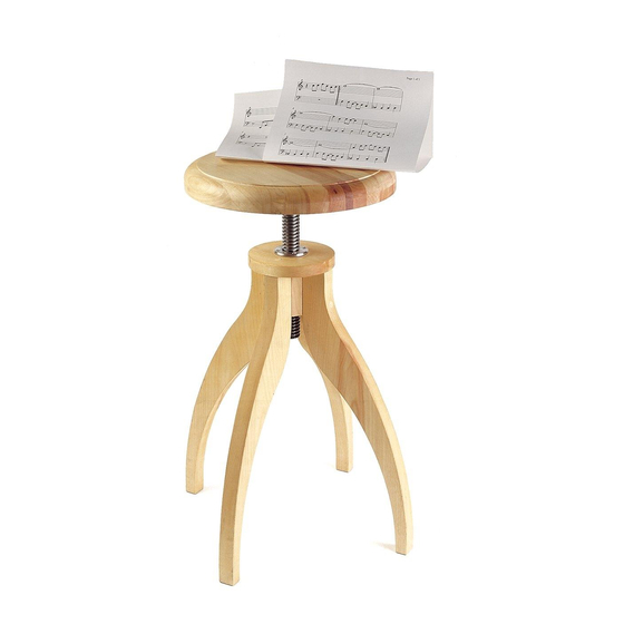
four. Our example shown in Figure 1 has four legs, with a 16"
diameter footprint and a 12" diameter seat. Figure 2 gives a top
view illustration, showing that a three-legged stool should have a
larger-diameter footprint than the four-legged stool.
The height of the leg/base/cap assembly should be approximately
2" shorter than the desired overall height of the piano stool when
the threaded shaft is fully lowered into the nut. The leg/base/cap
assembly shown in Figure 1 is 18", and yields a piano stool that
is 20" high when the threaded shaft is fully lowered into the nut,
and 26" high when it is fully raised.
The wooden base should be large enough to accommodate the
nut, which is 3" long with a 1.245" outside diameter and a 2"
diameter fl ange. (Our example has a 2" × 2" × 3" long base.) To
drill the hole in the wooden base, you will need a 1
(e.g., spade, forstner, saw tooth) with a shank length of at least
4". The diameter of the hole should be just large enough for the
nut to slide in easily without having to force it in. An oversized
hole, however, may cause the mounting screws to break out of
the sidewalls, preventing them from fully engaging in the wood.
We recommend you test the accuracy of your drill bit in a piece of
scrap wood (of the same material you will use to make your piano
stool). Dry fi t the nut into the test piece. If the fi t is tight, gradually
make the hole larger with a half-round fi le or with sandpaper
wrapped around a piece of 1" diameter dowel. When you are
satisfi ed with the fi t, make your base, and drill a hole through the
center of the base (repeating any adjustments that were required to
achieve a good fi t). It is important that the hole be on center. While
a hand drill should produce acceptable results, we recommend
you use a drill press if possible. Insert the nut into the hole to test
the fi t, and make any further adjustments as required. Remove the
nut and set it and the base aside.
The cap in our piano stool example in Figure 1 is 5" diameter by
1" thick. Drill a hole through the center of the cap (repeating any
adjustments that were required to achieve a good fi t). Insert the nut
into the hole to test the fi t, and make any further adjustments as
required. Remove the nut and set it and the cap aside.
Figure 1: Stool overview.
1
/
" drill bit
4
Figure 2: Footprint of legs.
1
Four-legged stool with legs
outside seat diameter.
Seat
Seat
Three-legged stool with legs further
outside seat diameter than four-legged version.
01K71.01
Seat
12" dia., 1" thick
Seat Base and Threaded
Shaft Assembly (supplied)
Steel Nut 1.245" dia.,
3" long (supplied)
Cap
5" dia., 1" thick
Base
2" × 2" × 3"
Legs
17" × 7" × 1" thick
Leg
Footprint
of Legs
Leg
Advertisement

Summary of Contents for Lee Valley 01K71.01
- Page 1 Piano Stool Hardware Kit 01K71.01 This kit provides the key hardware components to make a height- Seat adjustable piano stool. It consists of a seat base and threaded 12" dia., 1" thick shaft assembly and a steel nut that provide a total seat adjustment of 6".
- Page 2 Figure 3: Nesting template to reduce lumber waste. #6 Flat-Head Wood Screws (4) Flange Steel Nut " dia. hole Assembled Leg/Base/Cap Figure 4: Securing nut in the leg/base/cap assembly. Lee Valley Tools Ltd. Ottawa ON K2H 1C2 Canada leevalley.com © Lee Valley Tools Ltd. 2018 551 INS-214_C...