Advertisement
Quick Links
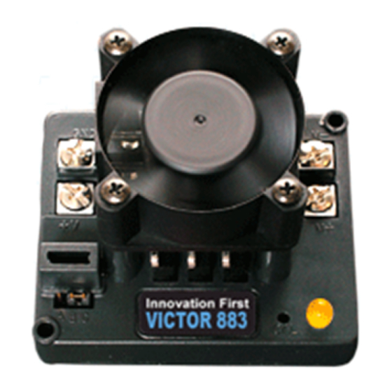
Innovation First
January 2001
The Victor 883 is a speed controller specifically
engineered for robotic applications. The high current
capacity, low voltage drop, and peak surge capacity make
the Victor 883 ideal for drive systems while its braking
options and precise control meet the demanding needs of
arms and lift systems. This controller safely handles the
high continuous current draws and extreme current surges
TO BATTERY GND
TO 30A BREAKER
and 12V BATTERY
Fan 12V (RED)
PWM EXTENSION CABLE
TO RECEIVER PWM OUT
Wiring Guidelines
You will need (4) #6 or #8 circle lugs (yellow) for
10AWG wire and (2) #6 or #8 circle lugs (red) for
20AWG wire.
1.
The fan must be wired so it is always ON when the
Victor 883 is ON.
2.
Attach (2) 20AWG circle lugs to the fan wires and
connect to the Victor 883 input terminals 12V and
GND.
3.
The input and output wires should be 10AWG wire
and firmly connected to ensure low voltage drop and
minimal temperature rise.
4.
Use circle lugs designed for 10AWG wire. The lug
should have a hole designed for a #6 or #8 screw. If
the center hole is too large, (#10 or larger)
inadequate mechanical contact may result in
excessively high resistance and temperature rise.
5.
Check all lug connection after crimping. You should
not be able to pull the lug off the wire with your
hands.
www.innovationfirst.com
GND
BLK
RED
12V
W B
R
B
C
Brake/Coast Jumper
produced by FIRST Competition robots. Innovative FET
switching architecture and an integral cooling fan ensures
cool FET junction temperatures. The low voltage drop
and high switching speed ensures the motor receives
maximum power, providing significant improvements in
acceleration, direction changes, and lifting torque.
Fan GND (BLK)
M
M
Innovation First
VICTOR 883
VICTOR 883
Cal Button
6.
Once the input and output wires are firmly
connected, tie the wires using tie straps within 2" of
the Victor 883. This will ensure the wires do not
move and loosen the connections.
WARNING: BEFORE APPLYING POWER:
1.
Ensure the input connections are not reversed.
Connecting 12V and GND backwards will
destroy the unit.
2.
Ensure that there is not a short circuit on the
output. A short circuit will destroy the unit.
3.
Ensure there is a 30A circuit breaker inline with
the 12v power input to the speed controller. This
ensures that long term exposure to a stalled
motor will not overheat the Victor 883.
Victor 883
Users Manual - Page 1
BLK
TO MOTOR
RED
LED Indicator Status
• Green = Full Forward
• Orange = Neutral / Brake
• Red = Full Reverse
• Flashing Orange = no PWM
LED Indicator
Advertisement

Related Manuals for Innovation First Victor 883


Summary of Contents for Innovation First Victor 883
- Page 1 FET junction temperatures. The low voltage drop the Victor 883 ideal for drive systems while its braking and high switching speed ensures the motor receives options and precise control meet the demanding needs of maximum power, providing significant improvements in arms and lift systems.
- Page 2 Brake / Coast Configuration Victor 883. A snug connection will hold the Victor 883 in place without crushing the case. The Brake / Coast jumper is used to set the Victor 883’s action during a neutral condition. The Brake provides Calibration Instructions...
- Page 3 The Inadequate travel in forward or reverse. Repeat the final test to determine if the Victor 883 is damaged is to calibration procedure and move the joystick further replace it with another Victor 883.
Need help?
Do you have a question about the Victor 883 and is the answer not in the manual?
Questions and answers