Table of Contents
Advertisement
Quick Links
Advertisement
Table of Contents

Related Manuals for VersaLogic EPM-PS1

Summary of Contents for VersaLogic EPM-PS1
- Page 1 Reference Manual DOC. REV. 4/29/2009 EPM-PS1 PC/104-Plus Power Supply Module...
- Page 2 All Rights Reserved Notice: Although every effort has been made to ensure this document is error-free, VersaLogic makes no representations or warranties with respect to this product and specifically disclaims any implied warranties of merchantability or fitness for any particular purpose.
- Page 3 Product Release Notes Rev 3 Release Charlie release EPM-PS1a model only–no battery backup function. Rev 2 Release Beta release. Rev 1 Release Pre-production only. No customer shipments. EPM-PS1 Reference Manual...
-
Page 4: Table Of Contents
Dimensions and Mounting....................7 Hardware Assembly....................8 Stack Arrangement Example ................. 8 External Connectors......................9 EPM-PS1 Connectors .................... 9 EPM-PS1 Connector Functions and Interface Cables ......... 11 Jumper Block ........................12 Jumpers As-Shipped Configuration..............12 Operation ........................13 Main Power Input ......................13 Power Out ......................... -
Page 5: Introduction
Introduction Features The EPM-PS1 is a DC switching power supply designed for high reliability in a wide variety of applications. The rugged design is conservatively rated to provide continuous 50 watt power output. When designing stacking PC/104-Plus compatible systems, OEMs and system integrators are able to develop entire systems using VersaLogic CPUs, I/O expansion modules and power supplies. -
Page 6: Technical Specifications
1.8W (150 mA) each max. continuous Output Protection: from -40° C to +85° C Current limiting and transient voltage Output Regulation: suppression 1% – all outputs Weight: 0.239 lbs (0.108 kg) Specifications are subject to change without notice. EPM-PS1 Reference Manual... -
Page 7: Block Diagram
Connector PC/104 (ISA) Pass- through Connector PC/104+ (PCI) Pass- through Connector Figure 1. EPM-PS1 Block Diagram Orange = Input Power. Red = 5V Output Power. Blue = ±12V Power Output. Green = Battery backup from battery card. * Battery backup feature is not implemented on the EPM-PS1a model. -
Page 8: Rohs-Compliance
(PBDE) flame retardants, in certain electrical and electronic products sold in the European Union (EU) beginning July 1, 2006. VersaLogic Corporation is committed to supporting customers with high-quality products and services meeting the European Union’s RoHS directive. -
Page 9: Transient Voltage Suppression (Tvs) Devices
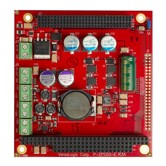
UPPRESSION EVICES The EPM-PS1 circuitry is protected from spike and surge damage by on-board transient voltage suppression (TVS) devices. In order for the TVS devices to function properly, they must be connected to earth ground. This connection is made at the board’s lower left mounting hole, as shown in Figure 2. -
Page 10: Technical Support
Introduction Technical Support If you are unable to solve a problem with this manual please, contact VersaLogic technical support at (541) 485-8575. VersaLogic technical support engineers are also available via e-mail at Support@VersaLogic.com. EPAIR ERVICE If your product requires service, you must obtain a Returned Material Authorization (RMA) number by calling (541) 485-8575. -
Page 11: Physical Description
Physical Description Dimensions and Mounting The EPM-PS1 complies with all PC/104-Plus standards, which provide for specific mounting hole and stack locations as shown in the diagram below. 3.575 3.375 0.125 DIA x4 Use 3mm or #4 standoffs 0.000 -0.200 Figure 3. EPM-PS1 Dimensions and Mounting Holes (Not to scale. -
Page 12: Hardware Assembly
SSEMBLY The EPM-PS1 uses PC/104 and PC/104-Plus connectors so that expansion modules can be added to the top of the stack. PC/104 (ISA) modules must not be positioned between the EPM-PS1 and any PC/104-Plus (PCI) modules on the stack. The entire assembly can sit on a table top or be secured to a base plate. When bolting the unit down, make sure to secure all four standoffs to the mounting surface to prevent circuit board flexing. -
Page 13: External Connectors
External Connectors EPM-PS1 C ONNECTORS PC/104-Plus (PCI) +9-40 VDC In Ground +5V Out Ground +12V Out -12V Out +12V Disable -12V Disable +5V Disable Ground PC/104 (ISA) = Pin 1 Figure 5. EPM-PS1 Connectors – Top Side EPM-PS1 Reference Manual... - Page 14 Physical Description PC/104-Plus (PCI) PC/104 (ISA) = Pin 1 Figure 6. EPM-PS1 Connectors – Bottom Side EPM-PS1 Reference Manual...
-
Page 15: Epm-Ps1 Connector Functions And Interface Cables
PS Control 16-14, to screw terminal 1. The PCB origin is the mounting hole to the lower left, as oriented in Figure 5. 2. Wire insulation should be chosen based on the application and safety agency requirements. EPM-PS1 Reference Manual... -
Page 16: Jumper Block
HIPPED ONFIGURATION Figure 7. Jumper Block Location – As Shipped Configuration Table 2: Jumper Summary Jumper Block Description Shipped Page [1-2] – Factory Use Only – This jumper must be installed or the EPM-PS1 will not operate. EPM-PS1 Reference Manual... -
Page 17: Operation
Operation Main Power Input Power is input to the EPM-PS1 through connector J3, which is a two-position, 5.08 mm screw terminal accepting AWG 16-14 insulated wire. Input voltage can range from 9V to 40V. Table 3: Main Power Input Connector Pinout... - Page 18 Operation Figure 8. PCI Connector (J2) Power Outputs EPM-PS1 Reference Manual...
- Page 19 Operation Figure 9. ISA Connector (J4) Power Outputs EPM-PS1 Reference Manual...
-
Page 20: Power Supply Control
All output voltages are on by default. To turn off a voltage, tie the voltage disable pin directly to ground. Disabling the +5V output turns off all outputs. Table 5: Power Supply Control Connector Pinout Signal +12V Disable -12V Disable +5V Disable Ground Efficiency and Derating Figure 10. Power Supply Efficiency over V and Load EPM-PS1 Reference Manual... - Page 21 Operation Ambient Temperature Figure 11. Power Supply Derating Curve EPM-PS1 Reference Manual...
-
Page 22: Appendix A - References
Appendix A – References PC/104 Specification PC/104-Plus Specification EPM-PS1 Reference Manual... - Page 23 Largest Supplier of Electrical and Electronic Components Click to view similar products for manufacturer: versalogic Other Similar products are found below : VL-CBR-ANT01 VL-SPX-2 EPMS-M1B VL-HDW-110 EPMS-M1C VL-SPX-3 VL-CF-CLIP1 VL-HDW-405 VL-CBR-1008 EPMS- M1A VL-CBR-0804 VL-MPES-S3E VL-CBR-1007 VL-EPM-PS1A VL-CBR-1012 VL-CBR-0803 EPMS-U1B VL-CBR-1201 VL-EPHS-...
Need help?
Do you have a question about the EPM-PS1 and is the answer not in the manual?
Questions and answers