Advertisement
Quick Links
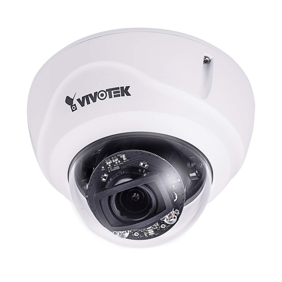
VIVOTEK FD9367-HTV (EPOC)
Installation Guide
Revison History:
Rev. 1.0: Initial release
Package Contents
Applications
RG6 100m ~ 2.4km
PoE switch
AP-FEX-0105-R
EPoC Rx Module
UPoE Injector
RG6 100m ~ 2.4km
Network switch
AP-FEX-0105-R
EPoC Rx Module
There are two cable routing options: A. through the bottom hole.
B. through the M20 conduit hole on the side.
A-1
Remove the original rubber
x3
seal by loosening 3 T10
screws. Push the seal apart
from the bracket.
Press the rubber seal assembly into place, and tighten the 3 T10
screws.
A-3
x3
Distance/Power Chart
AP-FEX-0105-T
Length of Coaxial Cable
AA-420 65W
300m
26.4W
500m
17.48W
800m
12.63W
AP-FEX-0105-T
1000m
8.84W
1200m
8.48W
EPoC Tx Module
1200m ~ 2400m
Data only (100Mbps)
AP-FEX-0200-T
Length of Coaxial Cable
AA-420 65W
100m
20W per port
300m
12W per port
500m
8W per port
500m ~ 2400m
Data only (100Mbps)
AP-FEX-0105-T
EPoC Tx Module
Open the included rubber seal grommet and pass the BNC
cable throught it (female to right-angle male BNC connector
cable).
A-2
Make sure the split on the seal grommet is on the outer side.
Move to Step 5
Installation
II
1
Jot down the camera's MAC address for later reference.
XXXXXX
0002D10766AD
3
Attach the included alignment sticker to a preferred position. Drill
holes on the wall and if space behind the wall allows, you may also
pass cables through the wall.
Leave 5mm of screw thread above the wall. This ensures easier
installation using the camera's keyhole slots.
AP-GIC-011A-095 95W
26.4W
17.48W
12.63W
8.84W
8.48W
Data only (100Mbps)
AP-GIC-011A-095 95W
20W per port
12W per port
8W per port
Data only (100Mbps)
If routing through an M20 conduit, remove the plug and install the
conduit. Route an RG6 coaxial cable through it. The M20 conduit is
user-supplied.
B-1
Keep for later use
Loosen the 2 screws securing the AP-FEX-0105-T EPoC module.
Lift it up a bit so that you can connect the BNC connector.
5
5
2
Open the top cover using a T10 L wrench.
4
Loosen the 3 T10 screws to remove the camera.
5mm
Use 2 seal rings when installing the conduit.
B-2
Seal ring x 2
M20
Move to Step 5
Connect the male connector on the cable to the counterpart on the
module. When done, secure the module back in place.
6
5
Advertisement

Summary of Contents for Vivotek FD9367-HTV
- Page 1 VIVOTEK FD9367-HTV (EPOC) Installation Open the top cover using a T10 L wrench. Jot down the camera's MAC address for later reference. Installation Guide Revison History: XXXXXX 0002D10766AD Rev. 1.0: Initial release Package Contents Attach the included alignment sticker to a preferred position. Drill holes on the wall and if space behind the wall allows, you may also pass cables through the wall.
- Page 2 Install the base chassis to the mounting screws you previously Replace the desiccant bag placed inside the chassis. Install the camera and top cover back to the base chassis. Please installed by aiming and turning counter-clockwise. When done, remember to attach the Ethernet cable between the camera and fasten the mounting screws.


Need help?
Do you have a question about the FD9367-HTV and is the answer not in the manual?
Questions and answers