
Related Manuals for NAVAC MASTER Series


Summary of Contents for NAVAC MASTER Series
- Page 1 5 Commonwealth Ave Woburn, MA 01801 Phone 781-665-1400 Toll Free 1-800-517-8431 Visit us at www.TestEquipmentDepot.com...
-
Page 2: Table Of Contents
The power must be cut off and no display in LCD before inspecting or repairing. If the original power supply cord is damaged, an OEM replacement may be ordered through your NAVAC distributor. Only a qualified person may replace the cord according to local codes and standards using OEM... -
Page 3: General Safety
N.AYf.AC N.AYf.AC Empowering you to work smarter Empowering you to work smarter GENERAL SAFETY OPERATION 1. Do not mix different refrigerants together in one tank, otherwise they could not be separated or used. Only authorized refillable refrigerant tanks can be used. It requires the use of recovery tanks with a minimum 2. -
Page 4: Specification
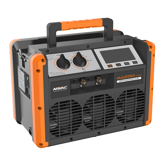
N.AYf.AC N.AYf.AC Empowering you to work smarter Empowering you to work smarter SPECIFICATION INTRODUCTION OF OPERATION PANEL NRDC4M =1111=1111 COMPLETE Category Ill: R-12, R-134a, R-401C, R-500 Category IV: R-22, R-401A, R-401B, R-402B, R-407C, R-407D, R-408A, Refrigerant Type R-409A, R-502, R-509 Category R-402A, R-404A, R-407 A, R-407B, R-41 OA, R-507 lnHgKpaPslKgfbarMPa... -
Page 5: Parts Diagram
NAVAC NAVAC Empowering you to work smarter Empowering you to work smarter PARTS DIAGRAM INTRODUCTION OF OPERATION PANEL • 1'JY-IAYSSTART�AT ACCaLDATION MAINKNO■ OPOSITION KNOii FAST ,Uc,1101! 11'.+ENUO I .IDI-WdMEROOCUFIS: PU•Ga • 1\,A,JAQCa..ERTlCNKNOEITOO • ,tOJUSTw.iNKNOBA0,,1.TO$ 01nV /\IN A cceleration Ofor initial recovery down to 36 psi inlet pressure Knob €)for fastest vapor recovery... -
Page 6: Wiring Diagram
N.AYf.AC N.AYf.AC Empowering you to work smarter Empowering you to work smarter OPERATING INSTRUCTION WIRING DIAGRAM 1 ). Refrigerant hoses purge I on. I Liquid valve on. I • � �Ii POWER SWITCH I � I U h1 Refrigerant ( NRDC4M ) ( Manifold gauge) equipment I�... -
Page 7: Recovery Mode
N.AYf.AC N.AYf.AC Empowering you to work smarter Empowering you to work smarter OPERATING INSTRUCTION OPERATING INSTRUCTION 2). Recovery mode 3). Purge mode Vapor valve Liquid valve A Notice c ap;enl l o�n(6) The unit must be purged after each use;Liquid refrigerant remained may expand and damage the components and pollute the environment. -
Page 8: Liquid Push/Pull Mode
7. Fault g or Fault 10 5. Check if TS connection is damaged. pressing START 8. Fault 11 If not, contact NAVAC techsupport. 6. Check if the connection between TP 9. Button is damaged 10. Circuit board is damaged and MCB is good. If good.