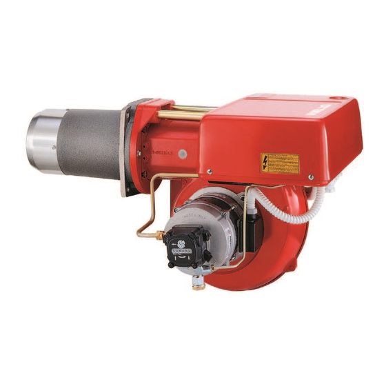
Riello PRESS 4G Installation, Use And Maintenance Instructions
Light oil burner
Hide thumbs
Also See for PRESS 4G:
- Installation, use and maintenance instructions (48 pages) ,
- Installation, use and maintenance instructions (44 pages)

Subscribe to Our Youtube Channel
Related Manuals for Riello PRESS 4G


Summary of Contents for Riello PRESS 4G
- Page 1 Installation, use and maintenance instructions Light oil burner CODE MODEL TYPE 3476582 PRESS 4G 609 T80 2915904 (3) - 03/2012...
-
Page 2: Technical Data
TECHNICAL DATA Thermal power 415 / 830 -1660 kW - 356.900 / 713.800 - 1.427.600 kcal/h Output 35 / 70 - 140 kg/h Fuel Gas oil, max. viscosity at 20 °C: 6mm /s (1.5 °E) ELECTRICAL DATA MOTOR IE1 MOTOR IE2 Three-phase 220V +10% -10% ~ 60Hz without neutral Electrical supply 380V +10% -10% ~ 60Hz with neutral... - Page 3 PRESSURE IN THE COMBUSTION CHAMBER - OUTPUT (in compliance with DIN 4787) Burner output kg/h The burner is drawn for on-off operation and high-low operation. Minimum firing-rate at on-off operation is 70 kg/h (two nozzles) and 35 kg/h (one nozzle) with high-low operation. DIMENSIONS OF THE TEST COMBUSTION-CHAMBER (DIN 4787) D = Boiler diameter in mm P = Position of the mobile...
-
Page 4: Hydraulic System
HYDRAULIC SYSTEM Gravity feed from the bottom of the oil storage tank The dimension P should not exceed 10 m, to avoid breakage of pump seals. L meters meters I.D. 12 mm I.D. 14 mm Gravity feed over the top of the oil storage tank The dimension P should not exceed 10 m, to avoid breakage of pump seals. - Page 5 BURNER ELECTRICAL WIRING (carried out by the factory) D10671 KEY TO LAYOUT Fan motor contact - maker Thermal cutout Photocell Ignition transformer Wiring terminal block Burner ground (earth) connection Fan motor stage solenoid valve Control box stage solenoid valve Suppressor 2915904...
- Page 6 ELECTRICAL CONNECTIONS TO THE WIRING TERMINAL BLOCK (to be carried out by the installer) 2647 220V 380V F Ampere S mm KEY TO LAYOUT Remote lock - out signal Limit control device system Wiring terminal block High - low mode control device system Lock - out reset button Safety control device system Burner ground (earth) connection...
- Page 7 FIXING OF THE ELECTRICAL WIRES All the electrical wires, which are to be connected to the terminal block 6) (fig. 1) shall pass through the fair leads 8) (fig. 1) as per this scheme. 1 - Three phase supply: fair lead Pg 21 2 - Single phase supply: fair lead Pg 13.5 3 - Adjustment thermostat:...
-
Page 8: Burner Adjustment
BURNER ADJUSTMENT Establish, on the basis of the output desired, and in accordance with the table and the diagram underneath: - the type of nozzle; - the pump pressure; - the combustion head setting. EXAMPLE The burner has to be matched with a boiler of 1000 kW. Assuming an efficiency of 90%, we need to develop approximately 1112 kW i.e. -
Page 9: Air Damper Adjustment
(3) The indicated outputs are drawn from the average statistical data of our tests. Real output may well vary by ± 5%. (4) The rear level of the control-shaft (7) (fig. 1) must line-up with the set-point number, indicated by the diagram. In the sketch on the right, the shaft is shown, in the position required by the example on page 7. -
Page 10: Priming The Pump
All burner controls are clearly indicated into the instruction. Only the air damper adjustment for the second flame, is determined at the place of installation, depending on the boiler pressure. ATTENTION At the first ignition, passing from the first to the second flame, the oil pressure decrease noticeably because of the filling of the second nozzle line - this decreasing can cause the burner shutdown, sometimes with strong pulsations. -
Page 11: Burner Start-Up Cycle Diagnostics
BURNER START-UP CYCLE DIAGNOSTICS During start-up, indication is according to the followin table: COLOUR CODE TABLE Sequences Colour code Pre-purging Ignition phase Operation, flame ok Operating with weak flame signal Electrical supply lower than ~ 170V Lock-out Extraneous light Key: Yellow Green OPERATING FAULT DIAGNOSTICS... - Page 12 RIELLO S.p.A. I-37045 Legnago (VR) Tel.: +39.0442.630111 http:// www.riello.it http:// www.rielloburners.com Subject to modifications...
Need help?
Do you have a question about the PRESS 4G and is the answer not in the manual?
Questions and answers