Advertisement
Quick Links
Advertisement

Related Manuals for Mod-Arte Flaunt FL03-70-110


Summary of Contents for Mod-Arte Flaunt FL03-70-110
- Page 1 Item Code-FL03-70-110 Assembly Instructions...
- Page 2 ATTENTION: Is your product damaged or missing assembly instructions? DO NOT RETURN!!!PLEASE READ THE FOLLOWING!!! For Replacement / Missing Parts: www.modarte.com/parts For Assembly Instructions and Assembly Videos:https://modarte.com/assembly/ All other enquiries, please send email to: operations@modarte.com or 973-264-1228 IF YOU ARE MISSING PARTS, OR PARTS ARRIVED DAMAGED: For fastest service, please contact us and we will mail you replacements parts the next business day.
- Page 3 Approximate time : 30 Minutes Surface should be uniform during assembly process. While door assembly ,ensure gap on all Four sides are equal. Mallet can be used to drive in dowel.
-
Page 4: Hardware List
HARDWARE LIST 8x40mm Wooden Dowel 16 pcs 6x35mm Minifix twister 8 pcs 15x12mm Minifix Roster 8 pcs 15mm Minifix Cap 8 pcs 6x50mm Shoulder Screw 8 pcs 3x16mm Screw 44 pcs 8x5x16mm Shef support pins 8 pcs 8x5x16mm Glass Holder 4 pcs Door Magnetic 2 pcs... - Page 5 TL 1 TL 6 TL 5 TL 4 TL 3 TL 7 TL 8 TL 7 TL 9 TL 10 TL 9 TL 2 TL 11 TL 12 TL 11 TL 11 TL 11 TL 11 TL 1 TL 14 TL 13...
- Page 6 Step 1 Attach Door Stopper (I) to part (TL1) using screw (F) with Screw Driver. Remove magnetic catcher plate for further use. Step 2 Attach Minifix Twister(B) to part (TL1) with Screw Driver.
- Page 7 Step 3 TL 11 GROOVE GROOVE GROOVE SIDE SIDE SIDE TL 11 TL 2 TL 12 LEG FRONT SIDE TL 11 TL 11 Check direction of leg while fixing follow the above pic along side and use screw(F) with screw driver. Step 4 TL 4 TL 6...
- Page 8 Step 5 TL 3 TL 4 TL 2 TL 5 TL 6 Attach parts (TL3,TL4,TL5,TL6) to part (TL 2) using screw(E). Step 6 TL 7 TL 8 TL 6 TL 5 TL 7 TL 4 TL 3 Slide Back Panel (TL7,TL8) into Grooves as per diagram...
- Page 9 Step 7 TL 1 TL 7 TL 8 TL 6 TL 5 TL 3 TL 7 TL 4 TL 2 Attach part (TL 1) to parts (TL3,TL4,TL5,TL6) then insert and secure Minifix Roster © to parts (TL3,TL4,TL5,TL6) to lock it. Step 8 TL 6 TL 1...
- Page 10 Step 9 TL 1 TL 4 TL 7 TL 8 TL 6 TL 3 TL 5 TL 7 TL 2 Insert shelf support pins(G) into (TL3,TL4,TL5,TL6) panel. Step 10 TL 1 TL 6 TL 5 TL 4 TL 9 TL 3 TL 9 TL 2 Place shelf on (TL9,) on top of support pins.
- Page 11 Step 11 TL 1 TL 5 TL 9 TL 4 TL 8 TL 6 TL 9 TL 3 TL 2 After shelf placement diagram Step 12 TL 14 TL 13 Attach handle (K) to parts (TL13,TL14) using handle screw(J) with screw driver and also magnetic catcher plate (I) with screw (F). Detail Steps 1.Insert screw in one of the hole meant for door handle and turn 1-2 thread only.
- Page 12 Step 13 TL 1 TL 3 TL 9 TL 9 TL 4 TL 13 TL 5 TL 2 TL 9 TL 6 Fix (L) as shown in diagram using (F) screw. Hinge Setting Required for Proper Door Closure. Step 14 TL 1 TL 9 TL 14...
- Page 13 Step 15 TL 1 TL 5 TL 14 TL 8 TL 13 TL 3 TL 2 TL 4 Insert glass holder(H) into part (TL4,TL5) Step 16 TL 1 TL 14 TL 5 TL 5 TL 8 TL 8 TL 13 TL 3 TL 10 TL 2...
-
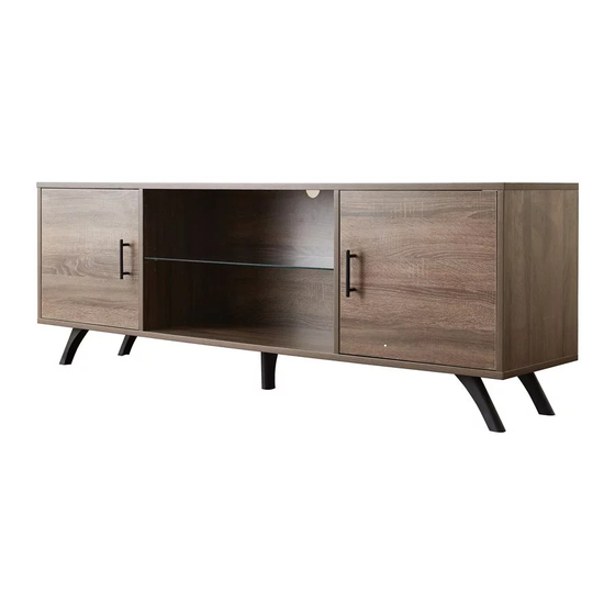
Page 14: Final Assembly
Step 17 FINAL ASSEMBLY TL 1 TL 5 TL 14 TL 8 TL 10 TL 13 TL 3 TL 2...
Need help?
Do you have a question about the Flaunt FL03-70-110 and is the answer not in the manual?
Questions and answers