
Summary of Contents for A.T.I.B. 883
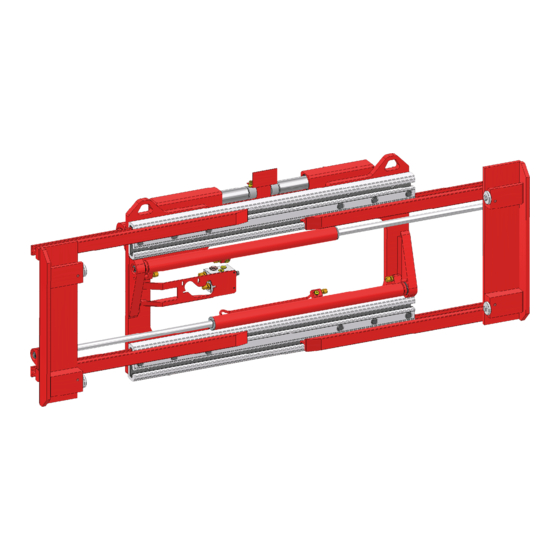
- Page 1 INSTRUCTION MANUAL FOR USE WIDE OPENING FORK POSITIONER TYPE 883 atib.com I-D02-01-65 - Rev.1...
-
Page 2: Table Of Contents
3 INSTALLATION ..........................8 Installation ........................... 9 3.1.1 Attachment installation - TYPE 883................9 3.1.2 Attachment installation - TYPE 883 with SLS ............12 Fork installation on attachment ..................15 3.2.1 Fork installation – TYPE “STANDARD” ..............15 3.2.2 Fork installation – TYPE “FB” ..................16 3.2.3 Fork installation –... - Page 3 7.2.3 Forks disassembly – TYPE “FS” ................30 Removal of fork cylinders from the attachment ............. 31 7.3.1 Fork cylinder disassembly and reassembly ..............33 Maintenance SLS cylinder ....................34 8 BREAKDOWNS AND SOLUTIONS ....................35 Breakdowns and solutions....................35 Lubricate ..........................36 Pag.
-
Page 4: Use Rules
1 USE RULES 1 USE RULES Don’t cross the mast Don’t carry passengers Swing 75mm Direction Don’t pass under the load Pag. 3 di 37... -
Page 5: Introduction
2.1 Use and upkeep of this manual This “User Manual” (hereinafter referred to as Manual) is supplied together with the A.T.I.B. - WIDE OPENING FORK POSITIONER TYPE 883 pursuant the CE DIRECTIVE 2006/42/CE date 17/05/2006 and amendments. The information contained here are imperative for the correct use of the attachment and must be known by the personnel who install, use, maintain and repair it. -
Page 6: Description Of Equipment
2 INTRODUCTION 2.2 Description of equipment TYPE 883 WITH SLS TYPE 883 TYPE 883 FS TYPE 883 FB Pag. 5 di 37... - Page 7 2 INTRODUCTION All the A.T.I.B. – WIDE OPENING FORK POSITIONER TYPE 883 equipment are identified by means of a sticky identification label on attachment (Tab 1) position of identification label on equipment (Picture 1), always refer to the serial number.
- Page 8 11. MAX COUPLE Not applicable to this equipment. The A.T.I.B. - WIDE OPENING FORK POSITIONER TYPE 883 were planned and built to enable the distance adjustment between fork centres through hydraulic actioning, all at the expected operating pressures unless otherwise indicated in the case of specific applications (see identification label).
-
Page 9: Installation
PORTATA (l/mm) Max operating TIPO and ISO Min. Max. racommended pressure (Bar) 883 ISO II [2400kg.@500mm.] 883 ISO III [3000kg.@500mm.] 883 ISO III [4500kg.@500mm.] 883 ISO IV [4500kg.@600mm.] 883 ISO IV [7000kg.@600mm.] Tab 2 WARNING!! RESPECT THE MAXIMUM WORKING PRESSURES INDICATED... -
Page 10: Installation
3. Check the condition of the pipes, replacing those that are in a bad condition. NOTE: The following figures show only the 883 standards, since the procedure for installing the equipment on the forklift is the same for welded forks and bolted forks type. - Page 11 3 INSTALLATION 5. For handling, use belts or chains appropriately sized for the weight of the equipment, indicated on the identification plate (Picture 1 and Tab 1 pag.6). Picture 3 6. With an overhead crane or with a hoist of sufficient capacity hook the attachment to the fork carriage, placing the centring tooth C into the central notch (Picture 3).
- Page 12 3 INSTALLATION 7. Screw the two bottom hooks G with bolts so that the attachment is safely mounted on the fork carriage P (with a tolerance max. 1,5mm Picture 4), reaching to the following torques Tab 3. ISO 2328 THREAD TORQUE ISO II 90 Nm...
-
Page 13: Attachment Installation - Type 883 With Sls
3. Check the condition of the pipes, replacing those that are in a bad condition. NOTE: The following figures show only the 883 standards, since the procedure for installing the equipment on the forklift is the same for welded forks and bolted forks type. - Page 14 3 INSTALLATION Picture 6 6. For handling, use belts or chains appropriately sized for the weight of the equipment, indicated on the identification plate (Picture 1 and Tab 1 pag.6). 7. With an overhead crane or with a hoist of sufficient capacity hook the attachment on the double hook, taking care to position the equipment correctly (Picture 7).
- Page 15 3 INSTALLATION ISO 2328 THREAD TORQUE ISO II 90 Nm ISO III 140 Nm ISO IV 220 Nm Tab 4 Picture 8 10. Insert the forks. 11. Lubricate the contact parts. 12. Connect the hydraulic circuit; making sure that the operating pressure of the pipes is higher than or equal to that indicated on the identification label (Picture 1 and Tab 1 pag.
-
Page 16: Fork Installation On Attachment
3 INSTALLATION 3.2 Fork installation on attachment 3.2.1 Fork installation – TYPE “STANDARD” Apply the forks after unscrew the fork blocks from fork holders TIPO “STANDARD” (Picture 9), according to the width of the forks, use the most appropriate fork stops (lateral or placed on the front part of the sliders). Picture 9 2. -
Page 17: Fork Installation - Type "Fb
3 INSTALLATION 3.2.2 Fork installation – TYPE “FB” TYPE “BOLTED 1. Relieve the pressure of the hydraulic system and disconnect the FORKS” pipes. 2. Apply the forks on fork holder, tightening the relative screws that lock them (Picture 11). Picture 11 3. -
Page 18: Fork Installation - Type "Fs
3 INSTALLATION 3.2.3 Fork installation – TYPE “FS” TYPE “WELDED 1. Relieve the pressure of the hydraulic system. FORKS” 2. Insert the forks, with the relative forks welded on them, and by the appropriate nut, fasten them to the cylinders (Picture 13). Picture 13 Check the correct locking of the forks (Picture 14). -
Page 19: Hydraulic System
4 HYDRAULIC SYSTEM 4 HYDRAULIC SYSTEM 4.1 Hydraulic system – TYPE 883 TYPE 883 CYLINDERS HYDRAULIC POWER SUPPLY Picture 15 Pag. 18 di 37... - Page 20 4 HYDRAULIC SYSTEM TYPE 883 WITH SLI CYLINDER POWER SUPPLY CYLINDERS Picture 16 Pag. 19 di 37...
-
Page 21: Hydraulic System - Type 883 With Sls
4 HYDRAULIC SYSTEM 4.2 Hydraulic system – TYPE 883 with SLS TYPE 883 WITH SLS SLS CYLINDER CYLINDERS HYDRAULIC POWER SUPPLY Picture 17 Pag. 20 di 37... -
Page 22: Use Rules
5 USE RULES 5 USE RULES Before using the equipment, check the tightness of the pipes and the correctness of assembly and connection by performing about ten preliminary operations. When using the equipment, it is necessary to follow the instructions listed below: 1. - Page 23 5 USE RULES In this occasion, we suggest to control the chart Picture 18, where, according to the increase of the centre of gravity (x-axis) there is a load reduction multiplying factor (y-axis). The multiplying factor, obtained based on desired load centre position, will be multiplied with nominal capacity of the equipment.
- Page 24 5 USE RULES The condition of the soil, the quickness of the movement of the load and the lifting height can affect the hold of the load and must be taken into consideration as regards specific occasions. Side shifting movement is forbidden in movement. Side shifting movement in condition of lifted mast is permitted only to bring back the load at the center of the mast.
-
Page 25: Integral Side Shift
5 USE RULES 5.1 Integral side shift It is one most frequently used in the WIDE OPENING FORK POSITIONER TYPE 883 and uses the same cylinders that translate the forks. The stroke depends on the opening and will be equal to zero in maximum opening and minimum closing. -
Page 26: Periodic Maintenance
6 PERIODIC MAINTENANCE 6 PERIODIC MAINTENANCE Failure to adhere to the norms and established times for maintenance operations, will be detrimental to the good functioning of the equipment and will annul the guarantee conditions. All maintenance operations must be carried out with the forklift motionless and the hydraulic circuit not activated, perimeter the entire maintenance area, using the necessary protective devices and, if it is necessary to disassemble the cylinders, always using a tray or container to recover the oil still present in the cylinder itself. -
Page 27: Maintenance Every 1000 Hours
6 PERIODIC MAINTENANCE 6.3 Maintenance every 1000 hours 1. Check the condition of upper and lower sliding devices if an excessively worn component is found, it is recommended to replace the entire assembly of the component in question. 2. Check the state of the sliding axis, making sure it is not scratched or deformed in any way 3. -
Page 28: Disassembly Procedure
7 DISASSEMBLY PROCEDURE 7 DISASSEMBLY PROCEDURE 7.1 Disassembly attachments from forklift 1. Relieve the pressure of the hydraulic system. 2. Remove the forks, following the operations indicated in the fork’s installation phase and attachment installation in reverse. 3. Unscrew the lower hooks of equipment (Picture 2 and Picture 6 pag.9 and 13). 4. -
Page 29: Forks Disassembly
7 DISASSEMBLY PROCEDURE 7.2 Forks disassembly 7.2.1 Forks disassembly – TYPE “STANDARD” 1. Relieve the pressure of the hydraulic system. TYPE “STANDARD” 2. Remove the forks after removing the fork holder (Picture 20). Picture 20 Pag. 28 di 37... -
Page 30: Forks Disassembly - Type "Fb
7 DISASSEMBLY PROCEDURE 7.2.2 Forks disassembly – TYPE “FB” TYPE “BOLTED 1. Relieve the pressure of the hydraulic system. FORKS” 2. Remove the forks after having unscrewed the relative screws that support them (Picture 21) Picture 21 Pag. 29 di 37... -
Page 31: Forks Disassembly - Type "Fs
7 DISASSEMBLY PROCEDURE 7.2.3 Forks disassembly – TYPE “FS” TYPE “WELDED 1. Relieve the pressure of the hydraulic system. FORKS” 2. Remove the forks after having unscrewed the relative screws that support them (Picture 22). Picture 22 Pag. 30 di 37... -
Page 32: Removal Of Fork Cylinders From The Attachment
7 DISASSEMBLY PROCEDURE 7.3 Removal of fork cylinders from the attachment 1. Relieve the pressure of the hydraulic system and disconnect the pipes. 2. Remove the forks after having unscrewed the relative screws that support them (Picture 23). Picture 23 3. - Page 33 7 DISASSEMBLY PROCEDURE 4. Remove the cylinders from their seats after unscrewing the relative nuts (Picture 25). Picture 25 Pag. 32 di 37...
-
Page 34: Fork Cylinder Disassembly And Reassembly
7 DISASSEMBLY PROCEDURE 7.3.1 Fork cylinder disassembly and reassembly If it is necessary to replace the entire cylinder, reassemble everything following the instructions listed in the previous point in reverse, if you also need to replace some cylinder component, proceed as indicated below: 1. -
Page 35: Maintenance Sls Cylinder
7 DISASSEMBLY PROCEDURE 7.4 Maintenance SLS cylinder 1. Relieve the pressure of the hydraulic system and disconnect the pipes. 2. Remove the attachments from forklift point 07.01 pag.27 3. Remove double hook (A) after having unscrewed the screws of the "protective fold" (P). 4. -
Page 36: Breakdowns And Solutions
8 BREAKDOWNS AND SOLUTIONS 8 BREAKDOWNS AND SOLUTIONS 8.1 Breakdowns and solutions FAILURE CAUSE SOLUTION Too low setting of the maximum Increase the pressure without exceeding pressure valve the maximum limit Insufficient pressure Contact the forklift manufacturer Insufficient strength Worn Pump Replace Worn cylinder seals Replace... -
Page 37: Lubricate
8 BREAKDOWNS AND SOLUTIONS 8.2 Lubricate 1. Lubricate the sliding parts using the special grease nipples. 2. Lubricate the slide and relative scroll bar. TYPE 883 Picture 28 TYPE 883 WITH SLS Picture 29 Pag. 36 di 37... - Page 38 A.T.I.B. S.r.l. Via Quinzanese snc 25050 Dello (BS) ITALIA Tel: +39 030 9771711 info@atib.com follow us atib.com I-D02-01-65 - Rev.1...
Need help?
Do you have a question about the 883 and is the answer not in the manual?
Questions and answers