
Summary of Contents for ELT eSMART iLC PRO 25/200 1050-XR Series
- Page 1 USER GUIDE Fully PROGRAMMABLE control gear for LED modules ORC < 5% elt@elt.es - www.elt.es GU-001/05/18-EN...
-
Page 2: Table Of Contents
6.2. 1-10V / 0-10V mode ......................17 6.3. ActiDIM mode ........................19 6.4. Corridor / Parking mode ..................... 22 6.5. ActiDIM mode with Corridor / Parking ................23 6.6. LineSwitch mode ......................... 24 6.7. MainsDIM mode ........................25 6.8. ON/OFF mode ........................26 www.elt.es... - Page 3 9. ELECTROMAGNETIC COMPATIBILITY 10. MECHANICAL FEATURES 11. DRIVER CONFIGURATION 11.1. iSOFT ..........................36 11.2. iProgrammer ........................36 11.3. Quick start guide ....................... 37 11.4. Factory default configuration .................... 38 12. MARKINGS AND INDICATIONS 13. APPLICABLE STANDARDS 14. PRODUCT WARRANTY 15. DISCLAIMER www.elt.es...
-
Page 4: Introduction
1.2. Applications ELT drivers with eSMART technology are the ideal street lighting solution of today and tomorrow, achieving optimal efficiency in every lighting point, accompanied by the best operational features and maximum energy saving, which... -
Page 5: Portfolio
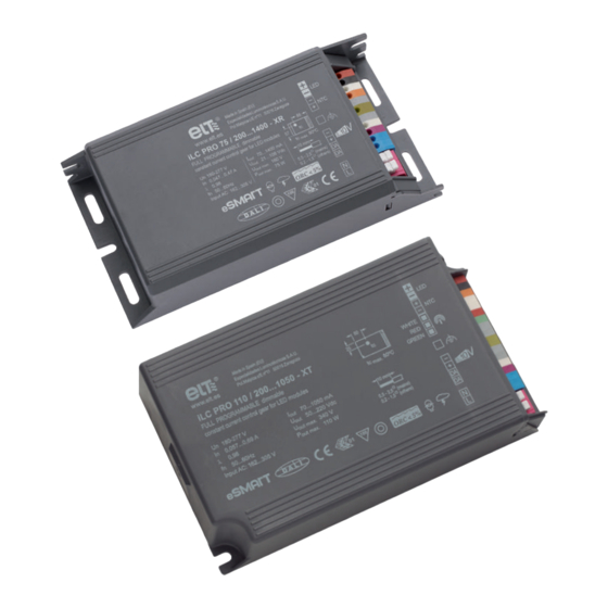
▪ Up to 100,000h lifetime. 1.5. Portfolio Ref nº Model Version compatible with the STELARIA remote wireless management system 9916164 iLC PRO 25/200...1050-XR 9916165 9916153 iLC PRO 40/200...1050-XR 9916154 9916151 iLC PRO 75/200...1400-XR 9916152 9916155 iLC PRO 110/200...1050-XT 9916166 iLC PRO 150/200...1050-XT www.elt.es... -
Page 6: Electrical Features
In terms of efficiency, the power factor, THD and dimming range of the iLC PRO drivers are positioned in the high performance segment of the lighting sector. NOTE: The technical specifications of each model and their corresponding data sheets can be viewed and are available for download via the ELT website at www.elt.es/en www.elt.es... -
Page 7: Electrical Insulation
Double Double Double NOTE: When the devices are built into luminaires, the cabling between the different components must observe the insulation class for which these lighting fixtures have been designed, as well as comply with the EN 60598 standard. www.elt.es... -
Page 8: Thermal Characteristics And Lifetime
The eSMART control gear can achieve up to a 100,000 hour lifetime depending on the working temperature at point NOTE: Thermal data and the lifetime of each model can be viewed on their corresponding data sheets, available for download via the ELT website at www.elt.es/en... -
Page 9: Protection
4. PROTECTION The eSMART technology control gear from ELT is equipped with internal protection to ensure that the drivers and every component of the luminaire in which they are installed operate correctly. 4.1. Short circuit protection In the case of a short circuit in the load terminals, the driver disconnects the power and goes into protection mode, in which it remains as long as the fault continues. -
Page 10: Out-Of-Range Mains Voltage Protection
If higher levels of protection are required, external devices can be added to the luminaire or to another point in the street lighting installation. NOTE: Fault conditions and the response of each model can be viewed on their corresponding data sheets, available for download via the ELT website at www.elt.es/en www.elt.es... -
Page 11: Functionalities
The output current value selected is understood to be the nominal value used to achieve 100% of the light level in any of the selected dimming modes that can be programmed within the entire permitted range. www.elt.es... -
Page 12: Led Module Thermal Protection (Mtp)
▪ NCP18XH103F03RB, 10k, 1%, 0805, MURATA. ▪ NCP15XW153E03RC, 15k + 390R series, 3%, 0402, MURATA. ▪ NCP18XW153J03RB, 15k, 3%, 0402, MURATA. ▪ NTCS0805E3153GMT, 15k, 2%, 0805, VISHAY. WARNING: connecting active signals to the external NTC terminals could run the risk of a breakdown. www.elt.es... -
Page 13: Led Module Constant Lumen Output (Clo)
To synchronise the compensation curve configured by the CLO with the actual lumen output depreciation, the MOT parameter, “the LED module operating time”, must be entered so that it coincides with the actual operating hours of the LED module. WARNING: The MOT value is also used for the EOL functionality. www.elt.es... -
Page 14: Led Module End-Of-Life Alarm (Eol)
5.5. Programmable start-up time (PST) This feature is able to configure a smooth and pleasant start-up, avoiding an abrupt sensation when the street lighting switches on. 100 % 50 % Time 30 seg. 600 seg. www.elt.es... -
Page 15: Monitoring Parameters And Events
LED modules its drives. Real time data recorded and the parameters can be monitored by the user via the iSOFT configuration software and by means of the STELARIA remote street lighting management system. www.elt.es... -
Page 16: Dimming Methods
The main features of each method are explained below. 6.1. DALI mode DALI (Digital Addressable Lighting Interface) is a digital and addressable communication interface for lighting systems, standardised in line with EN 62386 that guarantees the correct operation between devices produced by different manufacturers. www.elt.es... -
Page 17: 1-10V / 0-10V Mode
The analogue control signal is a continuous voltage level within a range from 0V to 10V. This signal can be obtained directly from an active control device (analogue control cards or power supply sources) or indirectly from a passive control device (variable resistance or potentiometer) through which the output current generated by the devices in their control terminals circulates. www.elt.es... - Page 18 However, the driver will respond to the set points as it enters standby if the selected dimming mode is 0-10V. NOTE: Drivers from different manufacturers may produce different responses to the same control signal value. www.elt.es...
-
Page 19: Actidim Mode
20 hours, the control gear does not memorise that period as a ‘night’ and therefore does not take it into account when applying the ActiDIM calculation algorithm. This system is able to configure different dimming profiles, selecting up to maximum of 9 levels, their value, the duration of the transitions and the changes between them. www.elt.es... - Page 20 ActiDIM mode. This function offers added value to the standard ActiDIM mode, as it allows the luminaire to operate with two different behavioural patterns with no need for control cabling to change from one mode to the other. www.elt.es...
- Page 21 ▪ The best results are obtained the wider and more focused the date range selected, as regards the solstices, in locations far away from the equator, when the installation is switched on and off at dawn and dusk as indicated by an astronomical clock that is not fast or slow. www.elt.es...
-
Page 22: Corridor / Parking Mode
DALI control terminals. The type of output offered by the sensor to be used must first be selected using the iSOFT configuration tool. Other parameters to configure are the dimming levels of the standby and detection statuses, the transition times between these statuses and the time it remains at detection level after which it fades out. www.elt.es... -
Page 23: Actidim Mode With Corridor / Parking
Level A Time NDT (No detection time) with presence NOTE: If, in the event a presence is detected, level A configured by the Parking mode is lower than the actual level of the ActiDIM mode, the ActiDIM level will prevail. www.elt.es... -
Page 24: Lineswitch Mode
In both cases, the required dimming level can be configured when the signal in the control line is detected or when it is not receiving. As a result the installation can be adapted to the desired dimming value in each case, defining the control “logic”. www.elt.es... -
Page 25: Mainsdim Mode
The use of this dimming method is recommended for installations with a peak value factor of 1.4142; supply voltages with peak factors other than the above will cause variations to the measurement of the mains voltage made by the control gear and as such, will create an advanced or out-of-phase action as regards the true RMS value. www.elt.es... -
Page 26: On/Off Mode
If the user configures the driver with an output current below 200mA by means of the AOC functionality, the driver will enter ON/OFF mode by default and no type of regulation will be allowed. www.elt.es... - Page 27 7. STELARIA REMOTE STREET LIGHTING MANAGEMENT SOLUTION STELARIA is a wireless point-to-point remote street lighting management system developed by ELT that showcases the features and functionalities of drivers equipped with eSMART technology, enabling remote control and monitoring of the luminaire’ s operation by means of the driver.
- Page 28 To give the user operational control of the luminaires, STELARIA offers an online lighting control based on a user- friendly, reliable and secure web application. This can be accessed at all times and from anywhere, from any device connected to the internet, providing accurate and immediate control of the street lighting infrastructures. www.elt.es...
- Page 29 IoT ecosystem. NOTE: For more information, please visit www.elt.es/en/stelaria-remote-wireless-street-lighting-cms www.elt.es...
- Page 30 The eSMART control gear, classified as “build-to-use” drivers, must be installed inside the luminaire or in other housings that guarantee protection from environmental conditions such as humidity, water, snow, ice and dust. ELT recommends the use of luminaires with a minimum protection rating of IP54, however depending on the application, higher protection levels may be necessary.
- Page 31 ▪ In Class I luminaires, the protective earth conductor is strictly compulsory. Connect the protective earth to the chassis and to the internal metal parts. ▪ In Class II luminaires, ELT recommends installing an equipotential connection or a star configuration functional earth conductor between the chassis and every inaccessible conductive element of the lighting fixture, to avoid issues with electromagnetic compatibility, to reduce residual brightness in the LED modules in standby mode and to provide protection against shock waves.
- Page 32 The inrush current values of the control gear will reduce, thereby increasing the number of drivers to be connected to each circuit breaker; the lower the voltage, the greater the impedance of the power grid (and vice versa). As such ELT recommends that it is checked for each installation.
- Page 33 ▪ Typically a maximum of 35 luminaires can be connected in a 30mA residential single-circuit trip switch. As this maximum number can vary depending on the installation , ELT recommends that this is checked. ▪ The functional earth terminal may not be disconnected from the driver to reduce the leakage current value.
- Page 34 ▪ Running a cable over or sticking it to the control gear is not recommended. ▪ ELT recommends that the functional earth of every metallic component of the luminaire is connected to the protective earth in Class I luminaires, even though this connection is not designed to protect from electric shocks.
- Page 35 10. MECHANICAL FEATURES iLC PRO -XR format Ø 4,2 74,3 10,8 129,1 140,5 iLC PRO -XT format 38,3 78,5 93,4 Ø 4,5 144,6 156,8 www.elt.es...
- Page 36 Thanks to the interface and configuration software, it is possible to make the most of the full flexibility and potential offered by ELT drivers equipped with eSMART technology, achieving solutions that perfectly adapt to the numerous and varied lighting applications that can be found.
- Page 37 Opcional para más de 4 equipos) WARNING: The iProgrammer programming interface connection to the iLC control gear must take place via the DALI terminals marked “DA”. The connection of the iProgrammer programming interface to other device terminals runs the risk of breakdown. www.elt.es...
- Page 38 Power-on 100% 2 hours before the middle of the night 1 hour before the middle of the night 4 hours after the middle of the night 5 hours after the middle of the night 100% Hour change Activated www.elt.es...
- Page 39 Indicates drivers that incorporate stand-alone and dynamic dimming that adapts to night hours. Indicates systems that regulate the light level by means of presence detectors. Marking for stand-alone dimming combined with presence detectors. Models with a maximum output voltage lower than 120V www.elt.es...
- Page 40 13. APPLICABLE STANDARDS The drivers manufactured by ELT with eSMART technology, ENEC tested and certified, have been designed in accordance with the following international standards: EN 61347-1 Lamp control gear. Part 1: General and safety requirements. EN 61347-2-13 Lamp control gear. Part 2-13: Particular requirements for DC or AC supplied electronic control devices for LED modules.
- Page 41 99/44/EC” from CELMA which establishes that: “It is understood that professionally installed ballasts and lighting are replaceable within a maximum of 10 minutes”). ▪ ELT reserves the right to request the return of the affected product to its premises in Zaragoza (Spain) to verify and subsequently validate the warranty claim.
- Page 42 Nevertheless, the appearance of editorial errors may not be ruled out, in respect of which ELT shall in no event be held liable. The reader is kindly requested to notify ELT of any error identified in this user guide.
- Page 43 Customer service - Export EASTERN EUROPE AND Tel. +34 976 573 660 CIS COUNTRIES Fax +34 976 574 960 Area Sales Manager: e-mail: cs-export@elt.es VICTORIA SYCHEVSKA Decin - Czech Republic Tel. +420 725 937 825 Customer service - National Email: vsychevska@elt.es Tel.
Need help?
Do you have a question about the eSMART iLC PRO 25/200 1050-XR Series and is the answer not in the manual?
Questions and answers