Table of Contents

Subscribe to Our Youtube Channel
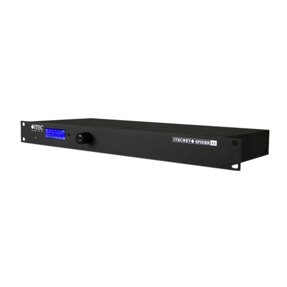
Summary of Contents for Itec ITECNET SPIDER 44/03
- Page 1 SPIDER 44/03 / SPIDER 04/03 SPIDER 44/03 / SPIDER 04/03 MANUAL Designed and Manufactured by ITEC Tontechnik und Industrieelektronik GesmbH 8200 Laßnitzthal 300 Austria / Europe SPIDER44/03 / SPIDER04/03_EN_2018/07_REV_2020/02...
-
Page 2: Dear Customer
For knowing the entire system, all its possibilities and for executing the necessary confi guration tasks the software manual is required in addition. Please observe during the installation / operation of the ITEC Spider 44 / Spider04 all listed safety instructions in this manual; furthermore data and examples provided ensuring the optimum usage of the device. -
Page 3: Safety Instructions
When installing the device, the local connecting conditions, the required protective measures and all relevant standards have to be observed. The installation and confi guration of the ITEC Spider 44 / Spider04 must be performed by trained personnel only. For the confi guration the original software ITEC NetDesign has to be used exclusively. - Page 4 At the same time, a huge number of system data, measurement data and IOs are controlled and transmitted. With four audio inputs, four audio outputs, serial ports and I/Os the Spider44 / Spider04 is one of the most important system components. www.itec-audio.com SPIDER44/03 / SPIDER04/03_EN_2018/07_REV_2020/02...
-
Page 5: Connectors On The Rear Panel
7 RS 232 interface 14 Speakers-line monitoring (optional) 8 External control inputs 15 Redundant Ethernet ports 9 Audio Inputs (only SPIDER 44) 16 AES / EBU Interface (optional, currently not available) 10 Power supply 24 V DC www.itec-audio.com SPIDER44/03 / SPIDER04/03_EN_2018/07_REV_2020/02... -
Page 6: Block Diagram
μP 0 dB IN 3 +30 dB ∞ OUTPUT UNIT 3 OUT 3 Delay ÷ +20 dBs +12V μP μP 0 dB IN 4 +30 dB ∞ OUT 4 OUTPUT UNIT 4 Delay ÷ +20 dBs www.itec-audio.com SPIDER44/03 / SPIDER04/03_EN_2018/07_REV_2020/02... -
Page 7: Audio Outputs
Phantom power is switchable per channel (12V). Optional 24V or 48V phantom power is possible with a plug-in module. Audio outputs The 4 outputs are balanced as well with XLR connectors on the rear cover. The maximum output level is +15 dB www.itec-audio.com SPIDER44/03 / SPIDER04/03_EN_2018/07_REV_2020/02... -
Page 8: Digital Inputs
The device has 8 digital open collector transistor outputs. They are used for switching relays, lamps of lo- wer power, etc. Typical applications are the display of faults, switching off other audio devices during an announcement and more. www.itec-audio.com SPIDER44/03 / SPIDER04/03_EN_2018/07_REV_2020/02... -
Page 9: External Control Inputs
B is used. The LEDs on the RJ45 connector show the operating status of the network connection: Green LED on: Connected Green LED fl ashing: Connected and network activity Yellow LED on: valid connection (100Mbps full duplex) www.itec-audio.com SPIDER44/03 / SPIDER04/03_EN_2018/07_REV_2020/02... -
Page 10: The Serial Interface
In case SPIDER 44/ the device is not operating or during a fault SPIDER 04 condition, the relay is released, during normal operation it is activated. Fault Relais max 48 V Fault Operating www.itec-audio.com SPIDER44/03 / SPIDER04/03_EN_2018/07_REV_2020/02... - Page 11 Deviations in the range 10 - 20% (adjustable) can reliably be detected. Using the impedance measurement, the return of the speaker wire to the terminals “RET” can be omitted. SPIDER 44 / SPIDER 04 Line Detection (Option) AUDIO-OUTPUT OUT 1 100 V POWER AMP www.itec-audio.com SPIDER44/03 / SPIDER04/03_EN_2018/07_REV_2020/02...
- Page 12 Ethernet 100 Base-TX, IEEE 802.3u No responsibility is taken for the correctness of this information - Specifi cations subject to change ITEC- Tontechnik und Industrieelektronik GesmbH, A-8200 Gleisdorf, Lassnitzthal 300 Tel.: +43 (0)3133 / 3780-0, offi ce@itec-audio.com, www.itec-audio.com SPIDER44/03 / SPIDER04/03_EN_2018/07_REV_2020/02...
Need help?
Do you have a question about the ITECNET SPIDER 44/03 and is the answer not in the manual?
Questions and answers