Table of Contents
Advertisement
Quick Links
Advertisement
Table of Contents

Related Manuals for Soluna S8 EU-A50


Summary of Contents for Soluna S8 EU-A50
- Page 1 User Manual Home Energy Storage System Soluna S8 EU Oct.2020| Revision A.1 1 / 52...
- Page 2 About this manual This manual describes how to install the Soluna S8 EU. Reading this manual before you attempt to install the product, and following the instructions throughout the installation process. If you are uncertain about any of the requirements, recommendations, or safety procedures described in this manual, contact Soluna immediately for advising and clarification.
-
Page 3: Table Of Contents
4.2.4 How to Setting parameters of Soluna system ..........36 4.2.5 How to check the information of “Data” icon............ 40 4.2.6 How to check the production information of Soluna system ......42 4.2.7 How to Check the fault information ..............42 5.How to operate the LCD (only for installer)... - Page 4 5.2 Grid parameters setting ..................44 5.3 Others ........................ 46 6.Caution ......................... 47 7.Troubleshoot ....................... 48 8.How to use the generator & AC couple function ..........52 9.Contact us......................52 4 / 52...
-
Page 5: Safety Precautions
1.Safety precautions Energy storage integrated machines are designed and tested strictly in accordance with relevant international safety standards. As an electrical and electronic device, all relevant safety regulations must be strictly complied during installation, operation, and maintenance. Incorrect use or misuse may result in: ●Injury to the life and personal safety of the operator or other people. -
Page 6: Warning Signs
1.1 Warning signs Warning signs are used to warn you about the conditions that may cause severe injury or damage to the device. They instruct you to exercise caution to prevent danger. The following table describes the warning signs used in this manual. Sign Name Description... -
Page 7: Safety Guide
1.2 Safety guide • After receiving this product, first confirm the product package is intact. If any question, contact the logistic company or local distributor immediately. • The installation and operation of the machine must be carried out by professional technicians who have received professional trainings, and thoroughly familiar with all the contents in this manual and the safety requirements of the electrical system. -
Page 8: Transportation And Installation
1.2.1 Transportation and installation • Keep the package and unit complete, dry and clean during storage and transportation. • This machine is heavy. Please remove and install it with at least Two people. • To ensure the normal and safe operation of the energy storage integrated machine and avoid personal injury, please select proper handling and installation tools, and take mechanical protection measures to protect personal safety, such as wearing smashing shoes,... -
Page 9: Maintenance And Replacement
1.2.3 Maintenance and replacement • Only qualified electricians are allowed to perform the maintenance, inspection, and component replacement of the machine. • Please contact the distributor or manufacturer for maintenance. • In order to avoid irrelevant personnel from entering the maintenance area during maintenance, temporary warning signs must be placed to warn non-professionals to enter or use fence for isolation. -
Page 10: Product Introduction
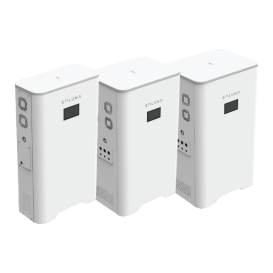
2.Product Introduction Soluna S8 EU Home Energy Storage System can connect with solar power generation system, which ensure the users can use environmentally-friendly energy 24 hours at any time. ESS store the energy generated by PV, and uses it whenever needed, not only reduce the purchase of electricity from the grid, but also improves the household energy self-consumption and saves the electricity cost. -
Page 11: Outline Dimensions
2.3 Outline Dimensions Figure 2.1 outline dimension Width Depth 1335 Height Weight 11 / 52... -
Page 12: Functional Description
2.4 Functional description 2.4.1 Basic principle of Soluna S8 EU Figure2.2 basic principle of Soluna S8 EU 12 / 52... -
Page 13: Working Mode
2.4.2 Working mode Soluna S8 EU has the following working modes for your home energy storage system. Mode 1: In daytime, PV power will charge the battery in priority, if battery is full, PV power is used to power the loads, then excess power sell to the grid. -
Page 14: Technical Data Of Battery Module
<2000 Cooling methods Forced airflow Ingress protection IP20 Condition Indoor conditioned IEC62109 AS/NZS 60950.1 Certificates EN61000-6-1:2007 EN61000-6-3:2007/+A1 CE-LVD EN 62477-1: 2012+ALL: 2014 Warranty Please refer to SOLUNA WARRANTY CONDITIONS 2.5.2 Technical data of battery module Physical Characteristics 14 / 52... - Page 15 Cycle life @ 25℃ ≥6000 (under standard charge and discharge conditions,charge 0.2C,discharge 0.2C) Contactor DC Disconnect Fuse Warranty Please refer to SOLUNA WARRANTY CONDITIONS <3W (work), Power consumption <100mW (sleep) System Voltage System Current Monitoring parameters Cell Voltage Cell temperature...
-
Page 16: Appearance
Max. 2,000 m Cooling Strategy Natural Convection Reliability & Certification Cell:UL1642 Certificates Battery Module:IEC62619 / UL1973 Transportation UN38.3 Ingress Rating IP20 2.6 Appearance ① ② Figure 2.3 Appearance Number Name Remark ① Soluna brand ② LCD panel 16 / 52... - Page 17 ① ② ③ ④ ⑤ ⑥ Figure 2.4 Appearance Number Name Remark ① FAN outlet ② FAN outlet ③ Emergency Stop ④ Handle ⑤ Incoming wire port ⑥ Label 17 / 52...
- Page 18 ② ① Figure 2.5 Appearance Number Name Remark ① Door lock of system ② Door key 18 / 52...
-
Page 19: Installation
3.Installation 3.1 Installation tools Item Photo Remark Marking pen Impact drill(φ12 mm) Steel tape Torque wrench (Opening size:13mm) Phillips-screwdriver (M6,M8) Straight screwdriver Multimeter Safety gloves Safety goggles Dust mask Safety shoes 19 / 52... -
Page 20: Installation Spacing
Min spacing Remark Side spacing 100cm There needs to be a clearance of 100cm on either side of Soluna system Back spacing 10cm It needs to be installed against the wall Note: For detailed requirements about the narrowest maintenance channel, escape route, etc., refer to the applicable standards of the country/ region where the... -
Page 21: Basic Installation Requirement
●There are no combustible gas and flammable materials nearby. ●The installation environment should be clean. 3.4.3 Installation procedures The mechanical installation steps are as follows: Step1 :user can find 2units of battery module and 1unit of the case of soluna after opening the packing box 21 / 52... - Page 22 ① ② Figure 3.1 Soluna system case & Battery units Number Name Remark ① System case ② Battery module 22 / 52...
- Page 23 Step2: The system is installed against the wall ③ ④ ② ① ⑤ Figure 3.2 Installation place Number Name Remark ① Wall ② Soluna System ③ Expansion Screw ④ Fixed Bracket ⑤ Ground 23 / 52...
- Page 24 Step3: Open the door of soluna system, and open the case of battery module ① Figure 3.3 System case ② Figure 3.4 Battery unit Number Name Remark ① System case ② Case of Battery module 24 / 52...
- Page 25 Step4: Push the battery module into the system, and lock the battery cable and plug in the CAN communication & Remote line. Details ① ② ③ Place of adding RJ45 terminal Figure 3.5 Connection for battery cable &CAN communication & Remote line Remark: Need add RJ45 terminal on CAN1 &...
- Page 26 1) All CAN1 lines are parallel for the internal communication of battery units 2) All CAN2 lines are parallel for the external communication . (between battery unit and hybrid inverter ),then,CAN2 is connected to inverter. Step 5: Fixed battery module and Close the door of Soluna system. ① ②...
- Page 27 Step6: external circuit connection (PV\Grid\Load) Figure3.8 external circuit connection ① Details ② ⑦ ④ ③ ⑤ ⑥ Number Name Remark ① Emergency Stop ② Load connector Back-up load connector ③ Grid connector ④ GEN connector ⑤ PV connector ⑥ GEN control port ⑦...
- Page 28 Only qualified PV strings under the local electrical safety laws and regulations and comply with the technical parameters of this manual are allowed to connect to the Soluna series energy storage integrated machines. the PV string connected to the energy storage integrated...
- Page 29 Only qualified AC transmission cables under the local electrical safety laws and regulations and comply with the technical parameters of this manual are allowed to connect to the Soluna series energy storage integrated machines Recommended wire specifications for safe system operation are as shown in the following table.
- Page 30 Step7 :Electrical connection 1) Soluna S8EU-A36 2)Soluana S8EU-A50 30 / 52...
- Page 31 CT connection ① ② ③ ③ Number Name Remark ① CT connector Connect to black wire of CT ② CT connector Connect to white wire of CT ② 31 / 52...
-
Page 32: How To Operate Soluna
4.How to operate Soluna 4.1Turn on or turn off Soluna S8 EU system Turn on: Open the door, and turn on all the switch of Load/Grid/Battery/Remote. Turn off: Open the door, and turn off all the switch of Load/Grid/Battery/Remote. Please find the following pictures for the position of switch. -
Page 33: How To Operate Lcd Screen (User Screen)
4.2 How to operate LCD screen (user screen) Users can only check Soluna system operating information and perform simple charge and discharge settings on the user screen, please find the following information for details. 4.2.1 Position of LCD ① Figure 4.2 LCD... -
Page 34: How To Check The Information Of Lcd Screen
4.2.2 How to check the information of LCD screen LCD screen including 5 icons. (Status、Settings、Data、Production information、Battery Capacity) Click each icon will see the relevant information. Please find the following picture for the interface of LCD screen. Figure 4.3 LCD Screen 4.2.3 How to check the information of “Status”... - Page 35 Figure 4.5 PV information Figure 4.6 Load information Figure 4.7 Grid information 35 / 52...
-
Page 36: How To Setting Parameters Of Soluna System
Figure 4.8 Battery information 4.2.4 How to Setting parameters of Soluna system clicking the icon of “Setting” . User find the following interface after Figure 4.9 Setting icon information User can find the following interface after clicking the icon of Power sources. - Page 37 Figure 4.11 Charging setting (1) Figure 4.12 Charging setting (2) Figure 4.13 Charging setting (3) 37 / 52...
- Page 38 The initial default charging speed is Regular (40A), Unless there are special circumstances. it is not recommended to use Very Fast to charge the battery. Low current charging is beneficial to prolong the battery life. User can find the following interface after clicking the icon of power utilizations.
- Page 39 The advanced settings are only opened to installers, and it is not recommended that end users enter into the advanced settings to set the parameters. User needs to confirm again it after setting the parameters of Soluna system. 39 / 52...
-
Page 40: How To Check The Information Of "Data" Icon
4.2.4 How to check the information of “Data” icon. User can find the following interface after clicking the icon of Data. a. User can find the following interface after clicking the icon of Solar generation. 40 / 52... - Page 41 clicking the icon of “back to grid”. b. User can find the following interface after clicking the icon of “Equivalent tree C. User can find the following interface after Planting”. clicking the icon of “save the earth”. d. User can find the following interface after 41 / 52...
-
Page 42: How To Check The Production Information Of Soluna System
4.2.6 How to Check the fault information User can find the fault information after click the fault icon Remark: User will find an icon blinking in the upper right corner of the LCD panel if there is any fault during Soluna system operation. 42 / 52... -
Page 43: How To Operate The Lcd (Only For Installer
The installer can set the Max charging and discharging current values according to actual needs. Meanwhile, “Use Battery V charged” & “Smart Lithium” should be ticked. 1) Shut down----- Soluna system will shutdown if the battery voltage below this value. 2) Low Battery------Soluna system will alarm if the battery voltage below this value . -
Page 44: Grid Parameters Setting
Grid charge “start V”------ Grid will start when the battery voltage is less than the “start V” in the condition of off-grid mode Grid charge “current”------ Current value that Grid charges the battery after started. 5.2 Grid parameters setting Select the correct Grid frequency accordingly, Otherwise Soluna system will not Work. 44 / 52... - Page 45 Charging and discharging time of Soluna system. Six periods can be set, from 0:00-24:00. Under “House load Only”, Do not tick” Grid Sell” Under ”House load+Back to Grid”, Tick ”Grid Sell”. Grid sell----The energy generated by PV supply house loads and battery in priority, excess energy would feed back to Grid.
-
Page 46: Others
5.3 Others Installer can find the Version information of Inverter hardware & Software. Solar Arc Fault on------ this is only for US market 46 / 52... -
Page 47: Caution
1)The Soluna system does not support parallel (three-and single-phase) operation on the AC-Backup, Parallel operation of the unit will void the warranty. 2) Single PV string Can’t be connected to 2 or more Soluna systems. 3) Back-up side can’t be connected to Grid. -
Page 48: Troubleshoot
7.1 Below are the descriptions of fault codes when system works abnormally. Find the table-1 for details. If any of the fault messages listed in Table-1 appear on Soluna screen and the fault has not been removed after restarting, Please contact installer or Soluna. - Page 49 Ac main contactor failure Ac secondary contactor failure Inverter 2 dc high fault AC Current over current AC Overload AC Grid Unavailable fault AC grid phase error Ac three-phase voltage imbalance failure Ac three phase current unbalanced failure AC Over current failure DC Over current failure AC Line W,U over voltage AC Line W,U low voltage...
- Page 50 7.2 The followings are common methods of troubleshooting. If problem haven’t been solved, Please contact Soluna. Table-2 Error code Description Solutions Working mode Inverter work mode changed change 1) wait for a minute and check. 2) Seek help from us, if can't go back to normal state.
- Page 51 2) Check the switch between inverter and grid is on or not; 3) Seek help from us, if cannot go back to normal state. Grid voltage fault 1) Check the AC voltage is in the range of standard voltage in specification; AC line low voltage 2) Check whether grid AC cables are firmly and correctly connected;...
-
Page 52: How To Use The Generator & Ac Couple Function
8.How to use the generator & AC couple function Soluna system have the function of diesel generator & AC couple. If the user who want use the diesel generator & AC function, please contact to us, following the engineers' instruction to operate.
Need help?
Do you have a question about the S8 EU-A50 and is the answer not in the manual?
Questions and answers