
Summary of Contents for RosRoca Olympus Mini
- Page 1 Olympus Mini Service Manual Stop engine before entering 855370B/1 855373B 855373B 855375B 855375B 855376B www.rosroca.com...
- Page 3 This Service Manual provides all the relevant service information and data necessary to carry out designated scheduled maintenance inspections and procedures on systems and components fitted to Ros Roca S.A. Olympus Mini Refuse Collection Bodies. The information in this Service Manual must be used in conjunction with the Service Manuals for the chassis‑cab and any ancillary equipment fitted to the refuse collection vehicle.
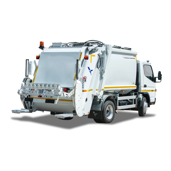
- Page 4 Ros Roca S.A. (The Company) reserves the right to description change the specification, design, material, procedure, The Olympus Mini refuse collection bodywork is a rear and dimensions of the equipment described herein loaded, fixed refuse collection bodywork manufactured without prior notice at any time in the future, in to EN 1501‑1.
- Page 5 CONTeNTS Olympus Mini Service Manual CONTeNTS PAGe Introduction ..........................1-1 Health and safety ........................2-1 daily checks ...........................3-1 Hydraulic system oil level ....................4-1 Cleaning ..........................5-1 Scheduled maintenance ......................6-1 Operational maintenance ....................7-1 General specification data ....................8-1 Supplementary information ....................9-1 index ............................I-1 OM1R-SM-GB01R...
- Page 6 CONTeNTS This page intentionally left blank OM1R-SM-GB01R...
- Page 7 INTROduCTION Olympus Mini Service Manual CONTeNTS PAGe Introduction ...........................1-3 Safety precautions ........................... 1‑3 Immobilising the vehicle prior to service procedures ..............1‑3 1‑1 OM1R-SM-GB01R...
- Page 8 INTROduCTION This page intentionally left blank 1‑2 OM1R-SM-GB01R...
- Page 9 This manual identifies all the recommended preventative maintenance service procedures and Before commencing any service procedure, the refuse inspections to be carried out on Olympus Mini refuse collection vehicle must be immobilised as follows: collection bodies. Stand the vehicle on clean, level and stable ground.
- Page 10 INTROduCTION This page intentionally left blank 1‑4 OM1R-SM-GB01R...
-
Page 11: Table Of Contents
HeALTH ANd SAFeTY Olympus Mini Service Manual CONTeNTS PAGe Health and safety ........................2-3 Introduction ..............................2‑3 Safety symbol, warnings, cautions and notes ................2‑3 Trained personnel ............................. 2‑3 Use of these instructions ........................2‑3 Precautions and protection for personnel ..................2‑4 2.5.1... - Page 12 HeALTH ANd SAFeTY This page intentionally left blank 2‑2 OM1R-SM-GB01R...
-
Page 13: Health And Safety
Olympus Mini refuse collection body. Precautions to be observed by personnel operating an Olympus Mini refuse collection body are contained in the equivalent chapter of the Olympus Mini Operator’s Handbook. It is everyone’s responsibility to make sure that they All Safety Information MUST be strictly adhered to. -
Page 14: Precautions And Protection For Personnel
HeALTH ANd SAFeTY Precautions and protection 2.5.2 Protective clothing for personnel Use and take care of all personal protective clothing and equipment supplied by your employer for your safety. 2.5.1 Personal hygiene 2. While operating or carrying out maintenance on a Personal hygiene is important at all times, particularly refuse collection vehicle, wear protective clothing for those working in the waste disposal environment... -
Page 15: Working At High Level
If in doubt, contact your local Health and Safety Officer. If access to components under the covers is required, remove them first as described in the appropriate sections of the Olympus Mini Workshop Manual. 2‑5 OM1R-SM-GB01R... -
Page 16: First Aid And Emergency Treatment
HeALTH ANd SAFeTY First aid and emergency treatment 2.7.4 Burns In the event of a skin burn, immediately administer the 2.7.1 workshop first aid equipment following emergency treatment: Run cold, clean water over the affected area. The workshop must be equipped with First Aid equipment complying with local legislation. -
Page 17: Workshop Precautions, Procedures And Practices
HeALTH ANd SAFeTY COSHH requires employers to: workshop precautions, procedures and practices • Assess the risks to health from hazardous substances used in or created by workplace activities. 2.8.1 Material safety data sheets • Not carry out work which could expose employees The European Commission’s Chemical Agents Directive to hazardous substances without first considering (CAD) (98/24/EC) establishes minimum health and... -
Page 18: Responsible Technician, The Key Holder
HeALTH ANd SAFeTY 2.8.2 Responsible technician, the Key Holder 2.8.4 General workshop precautions One person, the Key Holder, must be responsible Chock the vehicle wheels at all times when for the safety of all personnel involved when a maintenance work is in progress (Refer to vehicle is undergoing any form of maintenance chassis‑cab manufacturer’s Workshop Manual for work. -
Page 19: Moving Or Rotating Parts
HeALTH ANd SAFeTY 2.8.6 Moving or rotating parts 2.8.9 Fasteners There are risks of serious injury due to entanglement When assembling/refitting components using or collision with rotating parts such as fans, engine fasteners such as torque loaded bolts, nyloc nuts or components or propeller shafts. -
Page 20: Manual Handling And Movement Of Loads
HeALTH ANd SAFeTY 2.8.12 Manual handling and 2.8.13 Access and lifting equipment movement of loads Some maintenance tasks require the erection of access platforms and/or lifting equipment to provide a safe, All persons planning the lifting or movement of loads stable platform. -
Page 21: Fuel, Oil, Lubricants, Degreasants And Filters
HeALTH ANd SAFeTY 2.8.16 Fuel, oil, lubricants, 2.8.17 Solvents degreasants and filters Take special precautions when working with solvents, such as during cleaning and degreasant operations. Long term exposure of the skin to diesel fuel, Only use these materials in a well ventilated area. lubricating oils, hydraulic oil, lubricants and degreasants can cause problems such as dermatitis. -
Page 22: Cleaning A Vehicle
Vehicle electrical systems Wear protective clothing, gloves and goggles when 2.10.1 General electrical precautions you clean the bodywork of an Olympus Mini refuse collection body. Loose debris may be ejected from Always ensure correct polarity when making cable the body and tailgate. -
Page 23: Disconnection And Reconnection Of Electrical Components
HeALTH ANd SAFeTY 2.11 welding on or near the vehicle 2.10.2 disconnection and reconnection of electrical components Exercise extreme care when carrying out welding operations. Electric arc welding will seriously damage Note the position of all the connectors before they any electronic items fitted to the vehicle. -
Page 24: Hydraulic And Pneumatic Systems
HeALTH ANd SAFeTY 2.12 Hydraulic and pneumatic systems Vehicle hydraulic systems operate at high pressures, some parts of the system are under pressure even whilst the vehicle is shut down. Use caution when working on the system and its components. Compressed air is dangerous when misused, and flexible hoses may whip when under pressure. - Page 25 CHeCKS Olympus Mini Service Manual CONTeNTS PAGe daily checks ...........................3-3 Daily safety checks ‑ refuse collection body ................. 3‑3 Daily safety checks ‑ waste container lifting device (when fitted)........3‑22 Daily safety checks ‑ footboard (when fitted) ................3‑24 Daily safety check ‑...
-
Page 26: Daily Checks
dAILY CHeCKS This page intentionally left blank 3‑2 OM1R-SM-GB01R... -
Page 27: Daily Safety Checks - Refuse Collection Body
The following daily safety checks must be carried inspection. out on an Olympus Mini Refuse Collection Vehicle to confirm the correct operation of the machine, its controls, safety circuits and interlocks, in addition to checks specified in the chassis‑cab manufacturer’s... - Page 28 dAILY CHeCKS 13. Switch the ignition ‘on’ only, do not start the 16. Switch on the warning beacons. engine. • Check that the warning beacons and their • The control screen should initialise and then associated warning lamps operate correctly display the ‘Body system off’...
- Page 29 dAILY CHeCKS 22. Press and release the ‘Work lamp’ switch. 23. Press and release the ‘Internal discharge controls’ switch. • Check that the tailgate loading lamps and all the work lamps fitted to the vehicle illuminate. • The screen should display the ‘Body discharge internal controls’...
- Page 30 dAILY CHeCKS 25. Press and hold the ‘Tailgate raise’ switch until the wARNINGS: tailgate is just out of its locks and then release the MAKe SuRe THAT YOu KNOw THe HeIGHT switch. OF YOuR VeHICLe wITH THe TAILGATe ANd wASTe CONTAINeR LIFTING deVICe, •...
- Page 31 dAILY CHeCKS 29. On the compaction mechanism control panel, press 31. Press in turn the: in turn the: ‘Start pack cycle’ push‑ ‘Start pack cycle’ push‑ button. button. 4552-OM1-R-GB-G1 4552-OM1-R-GB-G1 ‘Rescue’ push‑button. ‘Rescue’ push‑button. 4550-OM1-R-GB-G1 4550-OM1-R-GB-G1 • Compaction mechanism should not operate. •...
- Page 32 dAILY CHeCKS 34. On each compaction mechanism control panel, 35. Press and hold the ‘Tailgate raise’ switch. press in turn the: 01.06.2013 09:00:00 Hyd Öl Temp Grad C Hyd Öl Druck bar 210 Bar Keine Fehler No errors Keine Fehler No errors Keine Fehler ‘Start pack cycle’...
- Page 33 dAILY CHeCKS 37. Press and hold the ‘Tailgate raise’ switch until the tailgate is fully raised and then release the switch. 01.06.2013 09:00:00 Hyd Oil Temp Hyd_Oil_Pressure 210 Bar No errors No errors No errors No errors No errors 4648-OM1-R-GB-G1 •...
- Page 34 dAILY CHeCKS 40. Press the eject switch. Release the switch when the 41. Press the retract switch. Release the switch when ejection plate has reached the end of its travel. the ejection plate has reached the end of its travel. 01.06.2013 09:00:00 01.06.2013...
- Page 35 dAILY CHeCKS 42. Press the eject switch. Release the switch when the 43. Press each of the two push‑buttons on the ‘Tailgate ejection plate has reached the end of its travel. lowering’ control panel separately. 01.06.2013 09:00:00 Hyd Oil Temp Hyd_Oil_Pressure 60 Bar No errors...
- Page 36 dAILY CHeCKS 44. Press the two push‑buttons on the ‘Tailgate 47. Press the two push‑buttons on the ‘Tailgate lowering’ control panel simultaneously. lowering’ control panel simultaneously until the tailgate engages locks and then release the push‑ buttons. 4582-OM1-R-GB-G1 • Tailgate should rotate smoothly downwards about the hinge pins until it engages face of body, then lower into locks.
- Page 37 dAILY CHeCKS 49. Press and hold the ‘Tailgate raise’ switch until the 50. Press and hold the ‘Lower tailgate to 1 metre’ tailgate is fully raised and then release the switch. switch until the tailgate stops lowering and then release the switch. 01.06.2013 09:00:00 Hyd Oil Temp...
- Page 38 dAILY CHeCKS 51. Press the two push‑buttons on the ‘Tailgate 52. Press and release the return switch. lowering’ control panel simultaneously until the tailgate engages locks and then release the push‑ buttons. 01.06.2013 09:00:00 Hyd Oil Temp Hyd_Oil_Pressure 2 Bar No errors No errors No errors...
- Page 39 dAILY CHeCKS For each compaction mechanism control panel, carry • Compaction mechanism packer plate should out the following operations (55 - 61): open (1), carriage plate and packer plate should move downwards (2), packer plate should close 56. Check that pack cycle operates correctly according (3), carriage plate and packer plate should to variant.
- Page 40 dAILY CHeCKS Open system vehicles: 59. Release the push‑button while the carriage plate and packer plate are moving downwards. • Vehicles not fitted with light curtain. • Carriage plate and packer plate should stop • Vehicles fitted with light curtain and folding rave immediately.
- Page 41 dAILY CHeCKS For each ‘emergency stop’ push-button: 64. On each compaction mechanism control panel, press in turn the: • Cab control panel (x 1) ‘Start pack cycle’ push‑button. • Compaction mechanism control panel (x 2) 4575-OM1-R-GB-G1 Carry out the following operations (62 - 68): 63.
- Page 42 dAILY CHeCKS • Packer plate should open and carriage plate 67. Press the ‘Start pack cycle’ push‑button. move upwards simultaneously until it is fully open and fully unpacked. 4552-OM1-R-GB-G1 • Compaction mechanism should not operate. 68. Turn the ‘Body main’ switch ‘off’ and then ‘on’ again.
- Page 43 dAILY CHeCKS On vehicles fitted with an external discharge control wARNING: panel carry out the following operations (69 - 78): MAKe SuRe THAT YOu KNOw THe HeIGHT OF YOuR VeHICLe wITH THe TAILGATe 70. Press and release the ‘Internal discharge controls’ ANd wASTe CONTAINeR LIFTING deVICe, switch.
- Page 44 dAILY CHeCKS 73. While tailgate is rising, release push‑button before 76. Press the ‘Ejection plate eject’ push‑button. it reaches its fully raised position. Release the push‑button when the ejection plate has reached the end of its travel. • Tailgate should stop rising immediately the switch is released.
- Page 45 dAILY CHeCKS 77. Press the ‘Ejection plate retract’ push‑button. 78. Press the ‘Ejection plate eject’ push‑button. Release the push‑button when the ejection plate Release the push‑button when the ejection plate has reached the end of its travel. has reached the end of its travel. •...
-
Page 46: Daily Safety Checks - Waste Container Lifting Device (When Fitted)
dAILY CHeCKS 79. Press the two push‑buttons on the ‘Tailgate daily safety checks - waste lowering’ control panel simultaneously until the container lifting device (when tailgate engages locks and then release the push‑ fitted) buttons. Caution If one or more footboards is fitted, lower footboard(s) before operating waste container lifting device. - Page 47 dAILY CHeCKS 3. Operate the ‘Lifting device up’ push‑button. While the lifting device is lowering release the push‑button. • Check that the lifting device mechanism stops immediately and remains in the stopped position. 8. Operate the ‘Lifting device down’ push‑button until the lifting device reaches fully down position.
-
Page 48: Daily Safety Checks - Footboard (When Fitted)
dAILY CHeCKS With the operative still standing on the footboard, daily safety checks - footboard drive the vehicle forwards and steadily accelerate the (when fitted) vehicle. Check that the vehicle speed limiter engages The following Daily safety checks must be carried out and prevents vehicle exceeding 30 km/h. - Page 49 dAILY CHeCKS 10. Select reverse gear and check that one of the following occurs dependant on market: • reverse gear engages (vehicles fitted with autobrake function). • the brakes release (vehicles fitted with autobrake function). • the engine can be started (vehicles not fitted with autobrake function).
-
Page 50: Daily Safety Check - Safety Light Curtain (When Fitted)
dAILY CHeCKS 3. Turn the body main switch on: daily safety check - safety light curtain (when fitted) • LED A should turn green. If a safety light curtain is fitted, the following Daily • LED B should be off. safety checks must be carried out, in addition to •... - Page 51 dAILY CHeCKS 4. Observe the status displays in the top of the 6. Press and release the ‘Start pack cycle’ push‑ transmitter and receiver screens and insert a button. suitable soft test rod (1) into the light curtain at point X and steadily move the test rod around the path indicated by the arrows (See Fig.3‑2 Safety light curtain test path).
-
Page 52: Warning Labels
dAILY CHeCKS warning labels Stop engine before entering 855370B/1 855534B 855376B It is an offence for any person to ride on the rear of a moving vehicle 855377B6 Note: Label not fitted when footboards are fitted Stop engine before entering 855370B Refer to workshop manual before any... - Page 53 dAILY CHeCKS Hydraulic Oil PT No. 47812B Max. RIDE ON REAR WALK UNDER RAISED BINS HOLD OBJECTS BEING PACKED ONLY USE CLEAN OIL OF THE DO NOT CORRECT SPECIFICATION CLEAN UP ALL SPILLAGES PT. No. 10019961 ENTER BODY WITH ENGINE RUNNING WALK UNDER RAISED HOPPER REACH INTO BINS DRIVE WITH BINS RAISED...
-
Page 54: Explanation Of Pictorial Warning Labels
dAILY CHeCKS explanation of pictorial warning labels Lubrication point. Do not put fingers into hole. Maximum A‑weighted sound pressure level at operator’s work‑ stations. 3‑30 OM1R-SM-GB01R... - Page 55 HYdRAuLIC SYSTeM OIL LeVeL Olympus Mini Service Manual CONTeNTS PAGe Hydraulic system oil level ....................4-3 To check hydraulic system oil level ....................4‑3 4.1.1 Topping up hydraulic oil ........................4‑8 4‑1 OM1R-SM-GB01R...
- Page 56 HYdRAuLIC SYSTeM OIL LeVeL This page intentionally left blank 4‑2 OM1R-SM-GB01R...
- Page 57 HYdRAuLIC SYSTeM OIL LeVeL Hydraulic system oil level To check hydraulic system oil level It is most important that the level of fluid in the wARNING: hydraulic reservoir is maintained within the specified THe BOdY MuST Be eMPTY wHeN limits. CHeCKING THe HYdRAuLIC SYSTeM OIL LeVeL.
- Page 58 HYdRAuLIC SYSTeM OIL LeVeL 6. Switch the ignition ‘on’. • The screen will display the ‘Body system run’ mode. Engage the PTO (see chassis cab manufacturer’s operating instructions). 8. Start and run the engine. • The cab control panel will initialise and then 01.06.2013 09:00:00 Hyd Oil Temp...
- Page 59 HYdRAuLIC SYSTeM OIL LeVeL 11. When the compaction mechanism reaches the wARNING: point where the carriage plate is in fully lowered MAKe SuRe THAT YOu KNOw THe HeIGHT position and the packer plate is open, press an OF YOuR VeHICLe wITH THe TAILGATe ‘Emergency stop’...
- Page 60 HYdRAuLIC SYSTeM OIL LeVeL When the tailgate is out of its locks, the ‘Tailgate out‑ 17. Press the two push‑buttons on the ‘Tailgate of‑locks’ pictogram will display on the control panel lowering’ control panel simultaneously to lower the screen. tailgate fully into its locks. 2810-OL1-D-GB-G2 16.
- Page 61 HYdRAuLIC SYSTeM OIL LeVeL 21. Check the oil level. • The reservoir is fitted with two oil sight glasses. The upper glass is marked with black and red lines to show maximum (see Fig. 4‑1, A) and minimum (see Fig. 4‑1, B) levels respectively during normal operation.
- Page 62 HYdRAuLIC SYSTeM OIL LeVeL 2. Unscrew the filler cap (see Fig. 4‑2, 1). Top up as 4.1.1 Topping up hydraulic oil necessary to the correct level using new hydraulic If topping up is necessary, thoroughly clean: oil to the correct specification. •...
- Page 63 CLeANING Olympus Mini Service Manual CONTeNTS PAGe Cleaning ..........................5-3 Drains ................................5‑4 5.1.1 Body drain ..............................5‑4 5.1.2 Tailgate drains............................5‑4 Daily cleaning ............................5‑5 Pressure washing ............................5‑6 Cleaning the leachate tank ........................5‑6 Cleaning the light curtain units ......................5‑6 5‑1...
- Page 64 CLeANING This page intentionally left blank 5‑2 OM1R-SM-GB01R...
-
Page 65: Cleaning
CLeANING Cleaning NeVeR CLeAN THe SeAL AReA uNLeSS THe TAILGATe IS FuLLY PROPPed. The refuse collection vehicle and its ancillary equipment must be kept as clean as possible to MAKe SuRe THAT ALL BOdY ANd prevent potential health hazards and promote trouble TAILGATe dRAINS ARe CLOSed ANd free operation. -
Page 66: Drains
CLeANING drains 5.1.2 Tailgate drains There is a drain point on each side of the tailgate and 5.1.1 Body drain leachate tank (if fitted). The body drain is on the right‑hand side of the body at the front. 4683-OM1-R-GB-G1 Fig. 5-2 Tailgate drains Plug Type 4594-OM1-R-GB-G1... -
Page 67: Daily Cleaning
CLeANING 11. Tilt the cab (see Chassis‑cab Manufacturer’s daily cleaning Operator’s Handbook) Stand the vehicle on clean, level and stable ground 12. Release the anti‑loose clip (1). with sufficient clearance to allow for the tailgate to be fully raised. 13. Pull the electrical distribution cupboard outwards (2). -
Page 68: Pressure Washing
CLeANING Pressure washing Cleaning the leachate tank Caution: when pressure washing the Refuse Collection Vehicle, its chassis-cab, body, refuse compaction mechanism and any ancillary equipment, such as waste container lifting devices, do not allow the jet nozzle to approach closer than 1 metre. Clean the compaction mechanism and slide tracks by Pressure washing at least once a week as follows: Stand the vehicle on clean, level and stable ground... - Page 69 SCHeduLed MAINTeNANCe Olympus Mini Service Manual CONTeNTS PAGe Scheduled maintenance ......................6-3 Introduction ..............................6‑3 Operational maintenance ........................6‑3 Routine maintenance ..........................6‑3 Warnings ..............................6‑3 Maintenance summary ‑ body ......................6‑4 Maintenance summary ‑ waste container lifting device ............6‑5 Lubrication ..............................
-
Page 70: Scheduled Maintenance
SCHeduLed MAINTeNANCe This page intentionally left blank 6‑2 OM1R-SM-GB01R... -
Page 71: Introduction
SCHeduLed MAINTeNANCe Scheduled maintenance Routine maintenance To maintain the mechanism at peak operational Introduction efficiency and good condition: • The refuse collection mechanism and waste The refuse collection mechanism and waste container lifting device should be serviced container lifting device should be serviced only by according to the procedures and at the skilled engineers who have received the approved intervals specified in this chapter. -
Page 72: Maintenance Summary - Body
SCHeduLed MAINTeNANCe Maintenance summary - body Interval every every every every Year 6 weeks 12 weeks 2 Years every every (2400 (300 (600 (4800 week operating operating operating operating hours) Operation Reference hours) hours) hours) Clean body and tailgate. Page 5‑5 Daily safety check. -
Page 73: Maintenance Summary - Waste Container Lifting Device
SCHeduLed MAINTeNANCe Maintenance summary - waste container lifting device Interval every every every every Year 6 weeks 12 weeks 2 Years every every (2400 (300 (600 (4800 week operating operating operating operating hours) Operation Reference hours) hours) hours) Clean waste container lifting device. Page 5‑5 Daily safety check. -
Page 74: Lubrication
SCHeduLed MAINTeNANCe Lubrication Immobilise the vehicle (see ‘1.2 Immobilising the vehicle prior to service procedures’ on page 1‑3). 2. Remove the bolts securing the bottom of the packer plate pivot cover plates. Loosen the top bolts and open each cover (see Fig. 6‑1, A). 3. - Page 75 SCHeduLed MAINTeNANCe 11. If the vehicle is fitted with a waste container lifting device, clean the grease nipples (see Fig. 6‑2, 1) and lubricate with the recommended grease (Shell Retinax A / BP Energol LS2 or L2 / Castrol LM / Total EP2 / Energol HLP32).
-
Page 76: Power Take-Off Propeller Shaft Lubrication
SCHeduLed MAINTeNANCe 6.7.1 Power Take-Off propeller shaft lubrication wARNING: THe POweR TAKe-OFF eXPOSed SHAFT ROTATeS wHeN THe eNGINe IS RuNNING. Where a propeller shaft is used to connect the hydraulic pump to the power take off, grease nipples may be fitted to enable greasing of the universal joints and splined connection (see Fig. -
Page 77: Weekly Service Operations
SCHeduLed MAINTeNANCe weekly service operations The following service operations should be carried out once a week or more frequently when the Refuse Collection Vehicle is operating in severe conditions. The following service checks should be carried out in addition to the Daily service checks. 6.8.1 Clean the body and tailgate (see Fig. -
Page 78: Waste Container Lifting Device Maintenance
SCHeduLed MAINTeNANCe 6-week (300 operating 6.8.3 waste container lifting device maintenance hours) service operations Grease all lubrication points (see ‘6.7 Lubrication’ The following service operations should be carried on page 6‑6). out once every 6 weeks (300 operating hours) or more frequently when the Refuse Collection Vehicle is 2. -
Page 79: Check The Security Of Body Mounting Bolts
SCHeduLed MAINTeNANCe 6.9.1 Check the security of body mounting bolts Check that body mounting bolts are tightened to the specified torques, and spring lengths and gaps are correct. Spring Ref. Components Size length **/ gap ‡ mm Front body mounting bolts. M12 x 35 Front body mounting bolts M12 x 90... -
Page 80: Clean The Tailgate Proximity Switches
SCHeduLed MAINTeNANCe 6.9.2 Clean the tailgate proximity switches Remove the tailgate side covers and clean the tailgate proximity switches. • Carefully wipe any dirt away from the face of each proximity switch and its operating plate. 4592-OM1-R-GB-G1 Fig. 6-6 Tailgate proximity switches 6‑12 OM1R-SM-GB01R... -
Page 81: Hydraulic System Components Checks
SCHeduLed MAINTeNANCe 6.9.3 Hydraulic system components checks 6.9.4 electrical system checks Examine the following hydraulic system Examine all the electrical wiring looms, their components and their mountings for, security, connectors, wires and mountings for, condition, fractures, displacement, wear, distortion, cracks, security, fractures, displacement, wear, distortion, damage, leaks or corrosion. -
Page 82: Slide Block Checks
SCHeduLed MAINTeNANCe 6.9.5 Slide block checks Check condition of ejection plate slide blocks (1). • The maximum wear allowed for any of each slide block’s dimensions is 6 mm. 2. Check condition of carriage plate slide blocks (2). • The maximum wear allowed for any of each slide block’s dimensions is 6 mm. -
Page 83: Waste Container Lifting Device Checks
SCHeduLed MAINTeNANCe 6.9.6 waste container lifting device checks Remove the side safety guards, to gain access to components. wARNING: IF OPeRATING LIFTING deVICe wITHOuT SAFeTY GuARdS TO ACCeSS COMPONeNTS FOR INSPeCTION, STANd CLeAR OF LIFTING deVICe ANd TAKe eXTReMe CARe TO AVOId MOVING PARTS. 2. -
Page 84: 12-Week (600 Operating Hours) Service Operations
SCHeduLed MAINTeNANCe 6.10 12-week (600 operating 6.10.2 Tailgate checks hours) service operations Check that the tailgate is sitting square on the body. The following service operations should be carried out every 12 weeks (600 operating hours) or more 2. Check that the carriage plate assembly is sitting frequently when the Refuse Collection Vehicle is square in its tailgate. -
Page 85: Waste Container Lifting Device Checks
SCHeduLed MAINTeNANCe 6.10.3 waste container lifting device checks 6.10.4 Power Take-Off propeller shaft (if fitted) Remove the side safety guards, to gain access to components. Examine the power take‑off propeller shaft universal joints for security, worn bearings, damage wARNING: to grease seals and cracks. IF OPeRATING LIFTING deVICe 2. -
Page 86: Compaction Mechanism Cycle Time Check
SCHeduLed MAINTeNANCe 6.10.7 Compaction mechanism cycle time check Check the compaction mechanism cycle time as follows: Start engine. wARNING: MAKe SuRe THAT ALL PeRSONNeL ARe CLeAR OF THe BOdY, TAILGATe ANd ReAR OF THe VeHICLe. 2. Energise the compaction mechanism control panels (see Operator’s handbook, ‘Energising the control panels’). -
Page 87: 12-Month (2400 Operating Hours) Service Operations
Drain the oil from the hydraulic system and fill 4. High pressure oil filter. system with new oil. Refer to Olympus Mini Workshop manual for Thoroughly clean the area around the filters. procedure. 2. Immobilise the vehicle ‑ (see ‘1.2 Immobilising the vehicle prior to service procedures’... -
Page 88: 24-Month (4800 Operating Hours) Service Operations
12‑Week (600 operating hours) service operations and 12‑Month (2400 operating hours) service operations. Replace ejection plate slide blocks (1). • Refer to Olympus Mini Workshop manual for procedure. 2. Replace carriage plate slide blocks (2). • Refer to Olympus Mini Workshop manual for procedure. - Page 89 OPeRATIONAL MAINTeNANCe Olympus Mini Service Manual CONTeNTS PAGe Operational maintenance ....................7-2 Fuses and relays ............................7‑2 Maintenance screen ..........................7‑4 7.2.1 Entering a password ..........................7‑5 7.2.2 Adjusting the clock/calendar ......................7‑6 7‑1 OM1R-SM-GB01R...
-
Page 90: Operational Maintenance
OPeRATIONAL MAINTeNANCe Operational maintenance Fuses and relays The electrical distribution cupboard containing the fuses and relay is mounted at the left‑hand front of the bodywork. It is pivoted at its bottom outer corner and held in its stowed position by a gas strut at the bottom and an anti‑loose clip at the top. - Page 91 OPeRATIONAL MAINTeNANCe SPR1 CR10 SPR2 BC10 4687-OM1-R-GB-G1 Fig. 7-1 Main body box 7‑3 OM1R-SM-GB01R...
-
Page 92: Maintenance Screen
2748-DS002-OL1-D-GB-G2 2748-DS003-OL1-D-GB-G2 The maintenance screen is a password protected gateway which allows authorised technicians to access screens where changes to the system configuration can be made. For further information refer to the Olympus Mini Workshop Manual. 01.06.2013 09:00:00 09:00:00 01.06.2013... -
Page 93: Entering A Password
OPeRATIONAL MAINTeNANCe 3. Press the maintenance switch. 7.2.1 entering a password • The ‘Password’ screen should display. To enter a password to access ‘Maintenance’ screen. Make sure the vehicle is stationary with the parking brake applied, the ‘Body main’ switch ‘off’ and the ignition switched ‘off’. -
Page 94: Adjusting The Clock/Calendar
OPeRATIONAL MAINTeNANCe 3. If the value is not suitable, for example it shows 7.2.2 Adjusting the clock/calendar 100 when you want to change the time in steps Adjustment of the clock and/or calendar can only be of 1 hour, press the ‘Scale’ switch until the correct made from a password protected ‘Maintenance’... - Page 95 OPeRATIONAL MAINTeNANCe 5. Press ‘Set’. Press ‘Set’ to confirm the setting. Config. Date / Time Config. Date / Time 01.06.2013 09:00:00 01.06.2013 09:00:00 Hyd Oil Temp Hyd Oil Temp Hyd Oil Pressure 2 Bar Hyd Oil Pressure 2 Bar Year : 2013 Day : 01 Month : 06 Year : 2013...
- Page 96 OPeRATIONAL MAINTeNANCe 9. When all values have been changed, press ‘SET 10. Press the return switch to return to the Date’. maintenance screen. • The clock and or calendar on the screen will change to the new settings entered. Config. Date / Time 01.06.2013 11:15:00 Hyd Oil Temp...
- Page 97 GeNeRAL SPeCIFICATION dATA Olympus Mini Service Manual CONTeNTS PAGe General specification data ....................8-3 Body identification label ........................8‑3 Typical operation times ......................... 8‑3 8.2.1 Cycle time ..............................8‑3 8.2.2 Ejection plate ............................. 8‑3 8.2.3 Tailgate raise/lower ..........................8‑3 Noise level ..............................8‑3 Hydraulic pressures ..........................
- Page 98 GeNeRAL SPeCIFICATION dATA This page intentionally left blank 8‑2 OM1R-SM-GB01R...
-
Page 99: General Specification Data
GeNeRAL SPeCIFICATION dATA General specification data Typical operation times 8.2.1 Cycle time Body identification label Cycle time with an empty tailgate = 15 ‑ 16 seconds. The body identification label is attached to the front of the body on the lower right‑hand corner. 8.2.2 ejection plate The information on the label is shown below:... -
Page 100: Hydraulic Oils And Greases
GeNeRAL SPeCIFICATION dATA Hydraulic oils and greases Recommended hydraulic oil Temperature range ISO grade ISO Oil type ‑30° to +80° VG 46 HL mineral oil to UNE‑EN ISO 6743‑4: 2002 Recommended greases Application Manufacturer’s specification General lubrication Shell Retinax A BP Energol LS2 or L2 Castrol LM Total EP2... -
Page 101: Dimensions
GeNeRAL SPeCIFICATION dATA dimensions L1 L1 4698-OM1-R-GB-G1 Model OL-MINI-6 OL-MINI-7 OL-MINI-8 7,5 ‑ 8 8,5 ‑ 9 GVw chassis (TN) (1) 3500 ‑ 3800 2700 ‑ 2900 3100 ‑ 3350 Recommended wheelbase 700‑800 Recommended chassis height (mm) Body useful capacity (m 3040 3134 3219... - Page 102 GeNeRAL SPeCIFICATION dATA This page intentionally left blank 8‑6 OM1R-SM-GB01R...
- Page 103 SuPPLeMeNTARY INFORMATION Olympus Mini Service Manual CONTeNTS PAGe Supplementary information ....................9-2 9‑1 OM1R-SM-GB01R...
- Page 104 SuPPLeMeNTARY INFORMATION Supplementary information Supplementary information/owners comments This page has been left blank to enable supplementary information to be incorporated in the handbook or for the owner to make notes. 9‑2 OM1R-SM-GB01R...
- Page 105 SuPPLeMeNTARY INFORMATION Supplementary information/owners comments This page has been left blank to enable supplementary information to be incorporated in the handbook or for the owner to make notes. 9‑3 OM1R-SM-GB01R...
- Page 106 SuPPLeMeNTARY INFORMATION Supplementary information/owners comments This page has been left blank to enable supplementary information to be incorporated in the handbook or for the owner to make notes. 9‑4 OM1R-SM-GB01R...
- Page 107 SuPPLeMeNTARY INFORMATION Supplementary information/owners comments This page has been left blank to enable supplementary information to be incorporated in the handbook or for the owner to make notes. 9‑5 OM1R-SM-GB01R...
- Page 108 SuPPLeMeNTARY INFORMATION Supplementary information/owners comments This page has been left blank to enable supplementary information to be incorporated in the handbook or for the owner to make notes. 9‑6 OM1R-SM-GB01R...
- Page 109 INdeX Precautions and protection for personnel — 2-4 Personal hygiene — 2-4 Protective clothing — 2-4 Cleaning — 5-3 Safety symbol, warnings, cautions and notes — Body drain — 5-4 Cleaning the leachate tank — 5-6 Trained personnel — 2-3 Cleaning the light curtain units —...
- Page 110 INdeX Operational maintenance — 7-2 Warning labels — 3-28 Fuses and relays — 7-2 Maintenance screen — 7-4 Adjusting the clock/calendar — 7-6 Entering a password — 7-5 Scheduled maintenance — 6-3 6‑Week (300 operating hours) service operations — 6-10 Check the security of body mounting bolts —...
Need help?
Do you have a question about the Olympus Mini and is the answer not in the manual?
Questions and answers