Table of Contents
Advertisement
Quick Links
Tiger Box Expansion Chassis 4U24
Assembly Guide
Product Overview . . . . . . . . . . . . . . . . . . . . . . . . . . . . . . . . . 3
Tiger Box Expansion Chassis 4U24 Features . . . . . . . . . . 3
Package Content . . . . . . . . . . . . . . . . . . . . . . . . . . . . . 4
Hardware Overview . . . . . . . . . . . . . . . . . . . . . . . . . . . 4
Site Installation . . . . . . . . . . . . . . . . . . . . . . . . . . . . . . . . . . . 5
Unpacking The Expansion Chassis . . . . . . . . . . . . . . . . . 5
Installing The Expansion Chassis . . . . . . . . . . . . . . . . . . 6
Installing and Removing The Front Panel Bezel . . . . . . . . 6
Connect The Expansion Chassis to Tiger Box . . . . . . . . . . 7
Connecting The Expansion Chassis to The Power . . . . . . . 7
Powering On The Expansion Chassis . . . . . . . . . . . . . . . . 8
Hardware Monitoring . . . . . . . . . . . . . . . . . . . . . . . . . . . . . . . 8
Monitoring the Chassis Activity . . . . . . . . . . . . . . . . . . . . 8
Monitoring RAID Drives Activity . . . . . . . . . . . . . . . . . . . 8
Monitoring The Power Supply . . . . . . . . . . . . . . . . . . . . . 9
Post Installation Maintenance . . . . . . . . . . . . . . . . . . . . . . . . . 9
Replacing a Failed Drive . . . . . . . . . . . . . . . . . . . . . . . . 9
Replacing a Failed Power Module . . . . . . . . . . . . . . . . . . 12
Advertisement
Table of Contents

Related Manuals for Tiger Technology Tiger Box 4U24


Summary of Contents for Tiger Technology Tiger Box 4U24
-
Page 1: Table Of Contents
Tiger Box Expansion Chassis 4U24 Assembly Guide Product Overview ....... . . 3 Tiger Box Expansion Chassis 4U24 Features . - Page 2 TO THE TIGER TECHNOLOGY PRODUCTS, AND SPECIFICALLY DISCLAIM THE IMPLIED WARRANTIES OR CONDITIONS OF MERCHANTABILITY, Tiger Technology reserves the right to revise and improve its products as it sees fit. SATISFACTORY QUALITY, AND FITNESS FOR A PARTICULAR PURPOSE. This publication describes the state of this product at the time of its publication, and may not reflect the product at all times in the future.
-
Page 3: Product Overview
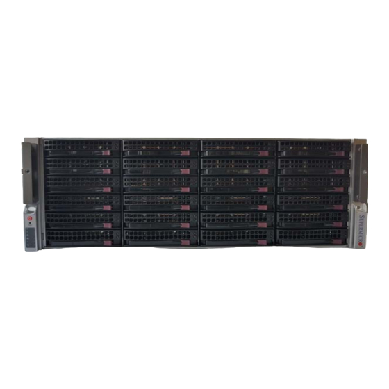
Tiger Box Expansion Chassis 4U24 is a natural addition to Tiger Technology’s all-in- one shared storage appliance, allowing you to easily expand the storage capacity of your Tiger Box. It features the same physical characteristics as Tiger Box 4U24 and is comprised of 24 enterprise-class drives (drive capacity depends on specific configuration). -
Page 4: Package Content
Product Package Content Important: If any of the components listed above is missing from your shipment, please contact your reseller or Tiger Technology support The palletized package you have received weighs approximately 44 kg (96 lbs) and has immediately. the following dimensions: Important: Check if both warranty stickers at the back of the chassis are intact. -
Page 5: Site Installation
Tiger Box Expansion Chassis 4U24 Assembly Guide Site Installation: Site Installation Rear View Apart from the 24 drive bays for the drives comprising the shared storage, the expansion chassis's front panel features the following elements: • LED indicators for monitoring system activity (see “Monitoring the The back of the expansion chassis features the following elements: Chassis Activity”... -
Page 6: Installing The Expansion Chassis
The same physical, electrical, and thermal requirements are valid for the Tiger Box • the expansion chassis receives adequate ventilation (it is not being installed in an expansion chassis 4U24 as for Tiger Box 4U24 (refer to Tiger Box 4U24 3.0 Assembly enclosed cabinet where ventilation is scarce);... -
Page 7: Connect The Expansion Chassis To Tiger Box
Tiger Box Expansion Chassis 4U24 Assembly Guide Site To remove the bezel: Note: To connect the expansion chassis to a Tiger Box appliance, which uses a MiniSAS port, you must use a External MiniSAS to External MiniSAS HD cable. Loosen the thumb screws on either side of the bezel. Should you decide to connect more expansion chassis (more than two with Tiger Gently pull away the bezel from the front panel of the expansion chassis. -
Page 8: Powering On The Expansion Chassis
Tiger Box Expansion Chassis 4U24 Assembly Guide Hardware Powering On The Expansion Chassis Once you have deployed the expansion chassis, you are ready to power it on. If the Indicator LED color Status Description Tiger Box/Tiger Box1 appliance to which it is connected is also turned on, the power fail LED solid power supply error... -
Page 9: Monitoring The Power Supply
Tiger Box Expansion Chassis 4U24 Assembly Guide Post Monitoring The Power Supply You can monitor the activity of the RAID drives using the LED indicators on the top of each HDD carrier: You can monitor the activity of the power modules using their LED indicator: Indicator LED color Status... - Page 10 Tiger Box Expansion Chassis 4U24 Assembly Guide Post shipped to you pre-installed in a drive carrier and is ready to replace the one that has Press the lever button on the front of the drive carrier to release the lever and gently pull out the drive carrier.
- Page 11 Tiger Box Expansion Chassis 4U24 Assembly Guide Post Press the lever release button on the front of the drive carrier. Find the label on the drive that specifies its corresponding drive bay and then slide the drive carrier into the corresponding slot until the lever makes contact with the enclosure.
-
Page 12: Replacing A Failed Power Module
Tiger Box Expansion Chassis 4U24 Assembly Guide Post Push the lever to finish sliding the drive carrier into the drive bay. To ensure that To check that the drive carrier is properly installed and makes full contact with the the lever is locked, you must hear a clicking sound. drive bay, try to pull it out without unlocking the lever. - Page 13 Tiger Box Expansion Chassis 4U24 Assembly Guide Post To replace a failed power module: Push back the lever of the power module to lock it. Find the failed power module (the light of its LED indicator is solid red). Unplug its power cable from the module's socket. Plug the power cable in the module's socket and power on the expansion chassis.
Need help?
Do you have a question about the Tiger Box 4U24 and is the answer not in the manual?
Questions and answers