Advertisement
Quick Links
Advertisement

Related Manuals for Sienci Labs LongMill V2

Summary of Contents for Sienci Labs LongMill V2
- Page 1 LongMill V2 Assembly Manual...
- Page 2 Table of Contents Part 1: XZ-Axis Gantry Part 2: Y-Axis Gantries Part 3: X-Axis Rail Part 4: Y-Axis Rails Part 5: Drag Chains and Wiring Part 6: Electronics Part 7: Table Mounting Appendix: Unboxing...
- Page 3 Tools you need Before you get started, here is a list of tools you should have on hand for assembly. Most people will have these tools in their shop: • Metric Allen keys or a drill and Allen driver bits • Pliers or metric wrenches • A small flat head screwdriver • Rubber mallet (optional)
- Page 4 Part 1 XZ-Axis Gantry...
- Page 5 Nut Assemblies Parts Needed: Delrin anti-backlash nut M5-25mm bolt M5-nylock nut Locking ACME nut & set screw Taking a look within your LongMill box, you should first look for a box at the bottom with a round orange sticker on it. Inside this box, you’ll find three hardware bags which are distinguishable by their sticker colour. For this first step, we’ll be using some of the hardware contained within the bags with the green and yellow stickers. In the yellow bag you’ll find a bag labelled for ‘M5-nylock nuts’ and another for ‘M5-25mm’ bolts, this is the M5 hardware you need. The green dotted bag will also have a bag of interest within it which contains 4 rectangular plastic blocks, grab this as we’ll be preparing these blocks for installing onto the XZ-axis gantry and eventually on the Y-axis as well.
- Page 6 The bag which had the backlash nuts will also contain a set of set-screws and nuts that are used to tension and reduce backlash. You can either install these or use some of the M5-25mm bolts, the set-screws are shorter so they don’t impede as much on the motion of the machine but they’re harder to get to for adjustment. If you’re not sure, go with the long M5 bolts for now then feel free to replace them with the shorter set-screws later on.
- Page 7 Z-axis motor sub-assembly Parts Needed: 3D printed Z-axis mount Steel Z-axis motor mount NEMA 23 motor 200mm lead screw (threaded) Previously Assembled 608ZZ flange bearing M5-25mm bolt M5-nylock nut ACME locking nut assembly 132mm GT2 closed loop belt 20T 6.35mm GT2 pulley 20T 8mm GT2 pulley Keep your M5 hardware nearby. Look back into the green bag to get the bag filled with flange bearings, and another containing two pulleys and a belt.
- Page 8 Start off by pushing in two M5-nylock nuts into the hexagonal holes in the 3D printed Z-axis mount. These will be used to mount the steel Z-axis motor mount. Make sure to keep the round part of the nut facing towards you when pushing them in. To the side, put the steel plate on the top of the motor, ensuring that its white connector is facing away from the middle-sized hole on the plate.
- Page 9 Fit the motor and plate assembly into the 3D printed Z-axis mount. If it doesn’t slide in easily, try sliding the motor all the way forward, and tilting the plate back slightly. You’ll know they’re aligned when their profiles match and they lay flush against each other. Moving the motor back and forth, and tilting the plate and motor back and forth can help get this part in place. Get the bag with bearings in it and use two when pressing them into the top and bottom bore on your assembly. You should be able to get them on easily with your thumbs. If you find resistance, try adjusting the steel plate so that the bores on the plastic and steel line up.
- Page 10 Bearing on the bottom Using two more of the same bolts, secure the plate and the 3D printed part together. These should thread all the way through to the nuts that you placed earlier in the plastic mount. Mount the steel plate to the 3D printed part.
- Page 11 The long, heavy box contains the rails, drag chains, and lead screws. Cut it open, remove the protective cardboard and shrink-wrap, and inside the bundle of lead screws you should be able to locate a very short lead screw which is what’s used for the Z-axis. With this in hand, get one of the ACME locking nut assemblies that you’d made before and thread the nut about 1.5 inches onto the lead screw. Make sure the nut still has its M3 set-screw. Next, slide the short end of the lead screw up through the flange bearings. It should slide in with little force; if you’re having trouble then try wiggling the lead screw back and forth gently.
- Page 12 Get the bag with a belt and two pulleys. You’ll find that only one of the pulleys will be able to fit over the lead screw but you’ll first have to unscrew the set screws a little with the included Allen key. Orient the pulley so that the base is flush with the end of the lead screw then tighten the screws into place. You might have to adjust the locking nut to make the lead screw and the top of the pulley flush. Use an Allen key to tighten the set screws to hold the lead screw.
- Page 13 Once the pulley is secure, twist the ACME locking nut in from the other side so that the pulley and the nut are sandwiching the two bearings. Once in place, tighten the M3 screw on the nut to hold it in place and ensure there’s no play up and down. Adjust and tighten if necessary. This step keeps the lead screw constrained in the z-axis. To put the belt into place: loosen the second pulley set screw, wrap the belt around it, slide the motor toward the lead screw, then wrap the belt around the first pulley and install the second pulley onto the motor shaft.
- Page 14 The base of the second pulley should be flush with the top of the motor shaft when tightened. Make sure to line up one of the set screws with the flat part of the motor shaft to provide extra holding strength (as shown in the photo). Next, make sure that the belt is tight around the two pulleys by pulling back the motor in the slot then tightening the M5 bolts that are holding it in place. Loose belt Tight belt...
- Page 15 XZ-axis gantry sub-assembly Parts Needed: Previously Assembled Anti-backlash assembly XZ-gantry assembly M5-25mm bolt Eccentric nut M5-nylock nut V Wheel M5 washer You should find the XZ-gantry assembly in a labelled bubble mailer. Once you take it out, you’ll see there’s a small steel plate (z-gantry) attached to big steel plate (x-gantry) via two sliding rails. First, check that the movement of your z-gantry is smooth by moving it up and down by hand.
- Page 16 Set the assembly to the side and get the green and yellow bags. In addition to the M5 bolts you have already used, the yellow bag should contain M5 washers. Inside the green bag is a set of 12 Delrin wheels. Spilling out the wheels, if you look down the center-hole you’ll notice that they have a bronze-coloured inner ring which can sometimes off-center (pictured).
- Page 17 You’ll also need two of the medium-sized M5 nuts from the last step and you’ll also need to grab eccentric nuts from the hardware bag labeled with an orange dot. These come in a small bag of 6 and are very odd looking so they should be easy to identify.
- Page 18 Now attach the bottom two v-wheel sets. These attach with regular M5-nylock nuts and need to be tightly fastened into place. You can do this with a size 4 Allen key and the included 8mm wrench. These are the two holes which we’ll put the next two v-wheels into. Install the v-wheels, ensuring that the washers are in place as well.
- Page 19 Tighten the wheels until snug. Once complete, all of your wheels will be facing the backside of your gantry. Check to make sure that each wheel turns smoothly. All of your wheels should be facing the same way.
- Page 20 There are two anti-backlash assemblies that attach to the XZ-gantry assembly. The first one we will assemble goes on the X-gantry. Two holes for mounting the anti-backlash nut block. Use two M5-25mm bolts (the same ones used to make the v-wheel sets) to mount the nut block. Make sure that the M5 nuts are facing outwards (pictured) so that you can see them. The block shouldn’t be tightened down really hard, just fasten it until it’s snug.
- Page 21 Now we’ll do the same process on the Z-axis on the two holes shown. Screw in the next nut block, making sure not to overtighten.
- Page 22 The completed assembly should look like this.
- Page 23 Connecting the two major sub-assemblies Parts Needed: Previously Assembled M8-25mm bolt M8 nut XZ-axis gantry sub-assembly Z-axis motor sub-assembly Get the motor sub-assembly from before. Holding it in one hand, and the gantry sub-assembly in the other, line up the lead screw from the motor assembly with the nut block of the gantry assembly. If you use your fingers to turn the lead screw, it will go into the nut. The plastic mount should be coming in from the side of the steel plate which has a rectangular notch cut out.
- Page 24 Continue turning the lead screw until the plastic, Z-axis mount is fully seated into the top of the plate and you can see the holes lining up. Shuffle the mount side-to-side or push it further into place to align the holes Get the M8 nuts and M8-25mm bolts from the yellow hardware bag; you’ll use a pair of each to fasten these two assemblies together. Take the two large nuts and push them into the back of the plastic Z-axis mount. If the nut fit is a little tight, then you can use a size 6 Allen key or other tool to press it into place.
- Page 25 Now with the two long bolts, slide them in from front through the two holes in the plastic mount. Turn them into place with a size 6 Allen key to secure the two assemblies together; the bolts should be reasonably tight. Fasten the M8 bolts. Keep a finger on the M8 nuts if you are finding they pop out when you first start tightening the bolt. Your assembly should now look like this.
- Page 26 XZ-axis gantry sub-assembly Parts Needed: Previously Assembled XZ-axis gantry assembly M5-12mm bolt Aluminum router mount Notice that the Z-axis gantry plate has two sets of four holes; these are positioned for mounting the aluminum router mount at two different heights. The lower set of holes will allow your router to gain more cutting depth, whereas the upper set will mount the router more rigidly and allow for the full height clearance. Use the upper set of holes to start.
- Page 27 With the current assembly turned around (looking in from behind) you’ll be able to place the four shorter bolts into the upper set of holes. Holding the router mount up to the bolts, you should be able to fasten it into place with a size 4 Allen key. The top set of holes in the Z-gantry looking in from behind the current assembly Use the four M5-12mm bolts to mount the router mount.
- Page 28 Your final assembly should look like this. Congrats, you’ve completed the assembly of the XZ-Axis Gantry! That was fun, wasn’t it?
- Page 29 Part 2 Y-Axis Gantries...
- Page 30 Y-axis gantries (wheels) Parts Needed: Previously Assembled Y-axis gantries Eccentric nut M5-nylock nut V-wheel set Grab the Y-axis gantries (wrapped in paper) and you’ll see four holes on each steel plate in a square formation. Add the wheel sub-assemblies to these holes just like how you did before, with the eccentric nuts placed as pictures and the nylock nuts on the two lower holes; make sure that one is assembled as the mirror of the other. Use a size 4 allen key and the included 8mm wrench to tighten everything down, but leave the eccentric nuts slightly loose for now.
- Page 31 V-wheel sets with a washer to keep the v-wheel spaced from the gantry plate Fasten the wheels to the eccentric nuts, leave these slightly loose for now...
- Page 32 Assemble the bottom two wheels with M5-nylock nuts and tighten all the way Make sure you have both plates done, but with the wheels on opposite sides.
- Page 33 Y-axis gantries (anti-backlash) Parts Needed: Previously Assembled M5-25mm bolt Y-axis gantries (with wheels) Anti-backlash assembly On the Y-axis plates, there are two holes for the anti-backlash assemblies to mount. Line up the plastic blocks and secure them to the plate using the same medium-sized bolts that were used for the wheels. The blocks should be mounted on the same side as the v-wheels, and have the tensioning screw facing outwards. The Delrin nuts go on the same side as the v-wheels do.
- Page 34 Tighten until snug. Don’t overtighten! Both sides should be mirrored.
- Page 35 Mounting the X-axis motor to the left plate Parts Needed: Previously Assembled Left Y-Axis Gantry NEMA 23 motor 3D printed drag chain mount 35mm aluminum M5-50mm bolt M5-nylock nut 6.35mm to 8mm 608ZZ flange spacer coupler bearing Make sure you have grabbed the correct gantry (pictured below).
- Page 36 We will put a 608ZZ flange bearing into the hole. Get a motor, the M5 nylock nuts from before, and the bag of long bolts (M5-50) and aluminum spacers from the orange bag. You will also need a coupler and bearing for this assembly, found in the green bag. Note that your coupler may be solid or jaw type, but they both work the same way (jaw type shown below). Start off by attaching the coupler to the motor shaft, making sure you have the smaller hole sliding onto the shaft and the larger hole facing up so that we can put the lead screw on later.
- Page 37 Carefully line up the screws into the four holes in the Y-axis gantry. Drop the motor, bolts, and standoffs into place. Take note of the position of the white motor connector in terms of its rotation and what side of the plate you are mounting it onto (the side with the wheels). Attach motor using M5 nylock nuts. Take note of the direction of the motor connector.
- Page 38 Use the four M5-nylock nuts to secure the plate-side of the M5 bolts. This requires a size 4 Allen key and the 8mm wrench. If it’s easier, start by finger-tightening all four nuts to keep everything in place before using the pliers to finish tightening. Among the group of plastic parts you should find one that has a thin ‘wing-like’ shape, this is the plastic y-axis drag chain mount. Grab this and clip it onto the aluminum spacers in the orientation shown. We’ve found that it is easiest if you clip on one side first, then swivel the other side on afterwards.
- Page 39 Once everything is finished getting put together, it should look like this: On to the next section!
- Page 40 Part 3 X-Axis Rail...
- Page 41 Preparing the X-axis rail Note: The 12×12 LongMill is a smaller build envelope so it doesn’t require an X-axis reinforcement bar. Move onto the next step “Attaching the Shoulder Brackets”, but keep in mind that the remaining pictures may show another piece of angled aluminum attached to the back of the X-axis rail. Pay no mind to this since the assembly process is otherwise the same.
- Page 42 Start by orienting the rails into a ‘lighting bolt’ pattern like in the photo so that the set of six holes on both can be aligned. Also, make sure to check that the small threaded hole on the X-axis rail (yellow) is oriented as shown so that you’ll be able to attach your drag chain later on. Grabbing the M8-16mm bolts from the orange bag, you can use six of these to fasten these parts together; the bolts will go through the larger holes on the reinforcement bar and thread into the X-axis rail from the back (pictured). Start by turning each of these short M8 bolts in by hand to get all the holes aligned, then go back and tighten each of them down well with a size 6 Allen key.
- Page 43 Your completed rail should now look something like this.
- Page 44 Attaching the shoulder brackets Parts Needed: Previously Assembled M8-16mm bolt 3D printed shoulder brackets X-axis rail Get the plastic, L-shaped ‘shoulder’ parts from the green box of plastic parts next. These go onto the two ends of the aluminum rail, each fastened with four of the same bolts as the last step (M8-16). Line each up with the holes first, with the flat part of the bracket facing out (pictured), before turning the bolts on by hand. Make sure to point the bracket in the right direction.
- Page 45 Finish securing the M8 bolts with a size 6 Allen key, being sure not to over-tighten them. Brackets attached on both ends...
- Page 46 Sandwiching the rail with the Y-gantries Parts Needed: Previously Assembled M8-25mm bolt X-axis rail M8 nut XZ-axis gantry assembly Y-axis gantries After the previous step, you should now have four major assemblies completed: the XZ-axis gantry, the two Y-gantries, and the X-axis rail. These assemblies will all be coming together in this step, starting by sliding the XZ- axis gantry assembly onto the X-axis rail. DO NOT stand the completed assembly up on the v-wheels, it can roll away or become unbalanced which may cause it to fall and become damaged; just leave it laying on its back for the next steps. You can consider propping it up at an angle as well if you don’t want the weight of the assembly pressing on the back of the Z-axis motor mount.
- Page 47 Before we start, you want to make sure that the eccentric nuts on the XZ-gantry are positioned correctly; this can be checked visually. Since the eccentric nuts have an offset hole point, rotating the nut will change the hole position. Looking at the gantry assembly from the front, this pictures shows the top, right eccentric nut at its lowest position.
- Page 48 Lay the X-axis rail down along its length with the inside of the ‘L’ shape facing you and the small, tapped hole oriented to your left. Now take the XZ-axis gantry and slide it onto the rail, being mindful of the plastic ‘arm’ that sticks out the back of the assembly since it’s prone to breaking in this position (pictured). XZ-axis gantry being slide onto the X-axis rail from the right-hand side The v-wheels fit over the aluminum rail as pictured below. Check that they are sitting on the rail in the correct fashion and make sure that they roll along the edge of the rail properly. Now the eccentric nuts need to be tensioned in order for the v-wheels to properly hold onto the X-axis rail. This process is just like before when you widened the eccentric nuts, except now...
- Page 49 Next, we’ll be putting the two Y-gantries onto each end of the X-axis rail. The orientation of each Y-gantry will be such that the wheels on the gantry will be facing towards the outside. Let’s start with the right-hand side. Line up the ‘L’-shaped slot on the steel plate with the rail and tap the plate into place. It works best if you put the slot and the rail head-on so that the slot and the rail line up straight. Note that because of the variance of paint thickness in the slot, you’ll chip some of it out as you mount the plate. These parts are a tight fit so that twisting in the X-axis can be kept to a minimum, so using a mallet and some coercion may be necessary but most importantly take your time.
- Page 50 Repeat the same process on the other side, being careful not to cause damage to the motor or the drag chain mount in the process. Now that the larger X-axis assembly is done, this is what the completed assembly should look like!
- Page 51 Adding the power transmission components Parts Needed: Previously Assembled Lead screw 608ZZ flange bearing 8mm washer ACME locking nut (530mm or 1030mm) assembly This step will attach the remaining components to the larger X-axis assembly. In the pictures, this step was done at a later time so the X-axis wasn’t laying down on a flat surface, but yours should still be. Since we moved this step to be earlier, pay no mind to the other parts in the picture.
- Page 52 Turn the lead screw into the nut with your hand. Push the lead screw into the opposite bearing. Dont push it all the way into the coupler just yet. Push the lead screw into the bearing...
- Page 53 Take an M8 washer (found in the orange bag) and line it up between the coupler and the bearing, and slide the lead screw through all three. Putting an M8 washer between the coupler and bearing.
- Page 54 Tighten the coupler to fully secure the lead screw to the coupler. Fully seat and secure the lead screw. Loosen the screw securing the coupler on the motor so that you can push it into the flange bearing. Use an Allen key or other tool to push the face of the coupler into the bearing. This will ensure that there is no play left and right in the lead screw.
- Page 55 Now on the other side of the X-axis rail assembly, take a second flange bearing and slide it into place as shown. It should fit into the bore on the right-hand side of the right-side steel plate. There should still be three ACME locking nut assemblies that you’ve previously assembled. Grab one of these and thread it onto the lead screw from the right, turning it all the way until it’s against the bearing, then tighten the set screw to hold it in place. Make sure the nut is really tightened into place before tightening its set screw.
- Page 56 This nut is used in combination with the coupler at the other end of the assembly to constrain the lead screw on the X-axis from moving side-to-side. As such, it’s a good idea to check that everything is secure by gently pulling on the lead screw to check for any looseness. Adjust the couplers and tighten the ACME lock nut more if you feel any play since you should be able to rotate the lead screw freely but not feel any side-to-side looseness.
- Page 57 Part 4 Y-Axis Rails...
- Page 58 Feet sub-assemblies Parts Needed: NEMA 23 motor 3D printed front feet 3D printed back feet 35mm aluminum M5-50mm bolt M5-nylock nut 6.35mm to 8mm 608ZZ flange spacer coupler bearing The two Y-axis rails mount to the machine base via a handful of plastic feet which require a bit of assembly before-hand. Start off by finding the front and back pairs among the plastic parts (pictured). These parts can be distinguished by their ‘zig-zag-like’ pattern with a thick base and by the embossed lettering denoting their position on the machine (e.g. “Back left” and “Back right”).
- Page 59 With the bearings still in hand from the last step, you’ll need to push one of them into each of the four feet. The front feet should have the bearings pushed in from the front, and the rear feet from the rear (pictured); make sure that you get the orientation right on these.
- Page 60 For the rear feet, we’ll also press-fit in eight M5 nylock nuts with the rounded side facing outwards. You should already have the bag of these medium-sized nuts open from earlier in the assembly. Put M5 nylock nuts into each nut catch on the rear feet Now, we’ll attach the two remaining motors to the rear feet. Install the coupler onto the motor first, followed by the long bolts and spacers that were used for the X-axis motor assembly. Loosely push the coupler over the motor shaft...
- Page 61 Install the bolts and spacers Move this over to the back of one of the rear plastic feet, orienting the motors white connector towards the flat base of the foot (pictured). Using a size 4 Allen key, you’ll be able to bolt the motor in place. Repeat the process for the other foot. Both feet with motors attached...
- Page 62 Completing the Y-axis Parts Needed: Y-axis rails Lead screws M8- 16mm bolt (500mm or 1000mm) (530mm or 1030mm) Previously Assembled Larger X-axis assembly Front and back feet ACME locking nut assemblies assembly The 30×30 LongMill comes with 1000mm long rails for the Y-axis, meanwhile the 12×12 and 12×30 models have 500mm long rails.
- Page 63 Secure the rear left and right feet assemblies (pictured) to one end of each rail. These can be secured using two of the short M8 bolts per foot assembly using a size 6 Allen key; the rails should be a mirror of each other. These rails need to now slide onto the larger X-axis rail assembly that you have set aside. To prepare for this, flip the X-axis assembly onto its front so that the router mount is contacting the ground; be sure that it’s stable in this position.
- Page 64 Now slide one rail onto the wheels of each of the Y-gantries from the back (pictured). Make sure that the flat side of the feet is pointing away from you so that, when completed, the machine is able to sit on the bottoms of the feet. Line up the inner profile of both sets of v-wheels to the edges of the rails in order to slide them into place Leave this sitting for a second while you collect the two front feet assemblies and four more M8-16 bolts (found in the orange bag) in preparation for this next step.
- Page 65 Next, thread the lead screws into place. It will go through the bearing on the front foot, threaded through the nut block on the Y-gantry, and through the bearing on the back foot. If you move the gantry to the back of the machine when doing this (pictured) it’ll require less time to thread it through. Thread the lead screw into the nut. Just like for the X-axis assembly, put a washer between the coupler and the bearing on the motor-side of the back feet.
- Page 66 Tighten everything down by pushing the lead screw all the way towards the motor shaft while pushing the coupler all the way towards the bearing, then tightening down the two set screws on the coupler to clamp down onto both sides. Ensuring that the face of the coupler/washer is flush against the bearing is important to prevent any play in the lead screw. Do this on both sides.
- Page 67 Attaching the middle feet If you have a 12x12 or 12x30 LongMill, there will only be one foot to attach to the right rail, which will only require 2 of the M8 bolts to attach it Parts Needed: 3D printed middle foot M8- 16mm bolt The last pieces to add are the middle feet. They look exactly like the back feet but exclude the backing. There are three of them and a fourth one that looks very similar but has another mounting point that juts out; this one will be used later in the assembly.
- Page 68 Part 5 Drag Chains and Wiring...
- Page 69 Drag Chains and Wiring Parts Needed: 1000mm drag chains 3D printed drag chain foot Router Motor wires M8-16mm bolt M4-16mm bolt M4 nylock nut We will now be installing the drag chains; these contain and guide the wires on the LongMill so that they aren’t in the way during cutting.
- Page 70 We’ll first start by removing the end connector links from both drag chains. You can either pull or squeeze off the connector as shown in the photos. A flat head screwdriver or thin shim can also be handy for this, just be careful not to cut yourself in the process. For the pin-type end link, squeeze the two sides of the link together, then twist and pull to disconnect For the hole-type end link, pull on one side of the link then twist it away to separate it...
- Page 71 Do this for all four end pieces, two hole-types and two pin types, and set them aside. We will attach these links to the machine, starting with the drag chain foot you set aside in the last step. It can be identified by its lightning bolt shape and the nut catches and wire clips it has on its back side. Also find the smaller M4 bolts and nuts in the yellow bag, as these will be used to attach the links in the following steps. Use a pair of bolts and nuts to secure the hole-type end link onto the drag chain foot in the orientation shown by using a size 3 Allen key. The nuts should fit into the hexagonal cutouts underneath the mounting point, meaning a wrench won’t be needed.
- Page 72 This last foot can now be attached to the Y-axis rails in the vacant space on the left side of the machine. Use two of the short M8 bolts to fasten it to the rail, similar to how all the other feet have been mounted. Drag chain foot mounted in place Now get a pin-type end link (pictured) to mount the other end of the drag chain. This one will attach the the X-axis clip-on mount where there’s a slot for the two bolts to fit through. Use pliers or a 7mm wrench to hold the nuts from the top while you fasten the bolts from underneath with a size 3 Allen key.
- Page 73 On the back-left side of the X-axis rail, you’ll find a hole to secure another drag chain link. You should only need one bolt to secure the pin-type end link using the tapped hole, but if your hole is not tapped, use an M4 nylock nut on the other side to secure the part. Find the hole on the X-axis rail to secure the drag chain link Use an M4 nylock nut on the other side of the aluminum angle if needed...
- Page 74 Lastly, we’ll attach the final drag chain end link onto the ‘arm’ of the Z-axis mount using another pair of M4 bolts and nuts. Note the direction the link is facing before installing it. Link fastened into place Next, we’ll be removing a couple of links on the drag chain. To do this, put your hands on either side of the link you want to break, then twist and pull them apart to disconnect. Set aside the remaining, unused links for later; they can come in use if you’re planning on upgrading to a larger sized LongMill later.
- Page 75 In the case of a 30×30 machine, we will remove 15 links off of the Y-axis drag chain, and none off of the X-axis drag chain. This will make it the correct length to mount at both ends when re-attached. Make sure to keep track of which chain is the shorter one so that you can re-attached them onto the correct axes.
- Page 76 One quick note, if you plan on adding more wiring into the drag chains in the future, it’s worthwhile to permanently remove every other cover tab since the wire will still be held in just as well but opening and closing them will take half the time. You can stick the extras into a baggy to save for later if you wish. All of the tabs unclipped and ready for wiring At this stage, it’s a good idea to grab the router you’ll be using with your machine. We’ll show these steps using the Makita RT0700 / RT0701 trim router that we recommend.
- Page 77 To mount your router, simply loosen off the two front bolts until you can fit the router in the mount, then tighten back up again to secure it. You can adjust the height later if needed. We recommend going back and forth between the two bolts to keep them parallel; and make sure not to over- tighten them. If you do over-tighten these bolts and start to strip the bolt head, these bolts can be substituted with the M5 bolts that came with your machine if you have any extras.
- Page 78 Grab the drag chain for the X-axis (the longer one for the 30×30) and seat the Z-axis motor and the router wire into the drag chain. Make sure that you have the correct end of the drag chain (with a pin-type link) so that you’ll be able to connect it to the mounted end link (pictured), and so that the drag chain can bend in the right direction against the X-axis.
- Page 79 Swing the drag chain and clip it onto the end link attached to the X-axis rail. Pull the wires through. Now attach a motor cable onto the X-axis NEMA 23 stepper motor.
- Page 80 We will take the cable from the X-axis NEMA 23 stepper motor and the Z-axis NEMA 23 stepper motor, as well as the router cable and insert it into the Y-axis drag chain. Clip the tabs in to secure the wires, and make sure that the drag chain is facing the right direction (with the hole-type link, pictured) to fit into the correct end links. Grab the Y-axis drag chain and insert the X and Z-axis motor cables and router cable Clip the both ends of the drag chain into the previously mounted end links on the Y-gantry and the drag chain foot.
- Page 81 Now plug in the cables for the motors on the two Y-axis NEMA 23 stepper motors.
- Page 82 Bring the cables around to the left of the machine and slot them into the wiring cutouts in the drag chain foot. With all of the wiring coming in from the left, he machine wiring should now be complete.
- Page 83 Part 6 Electronics...
- Page 84 The LongMill electronics come pre-assembled and are pretty much ready to go out of the box. However, we recommend double-checking a few things before powering-on. DC power supply connector polarity Before you plug in the power, check that the connection at the connector is correct and secure. The wire colours should be white or red on the left side and black on the right when the screw terminal is facing you (as pictured). Check that the wires are connected securely by tugging on them. Secure them using the screw terminals and a flat head screwdriver if they’re loose or disconnected.
- Page 85 Motor connector wiring The wires, looking down from the side with the screw heads, should be, from left to right, BLUE, YELLOW, GREEN, RED (pictured). Check if the color pattern on all four of your motor wires is correct and re-arrange them if needed. As previously, also check that the wires are connected securely to the connector. The wiring color pattern should be blue, yellow, green, red. While you’re at it, double check that the motor-side, white connectors on each axis are pushed all the way into the motor housing to ensure a good connection.
- Page 86 Properly seated DIP switches Looking at the underside of the control box, you should notice four red switch blocks on the circuit board through the slots in the steel (pictured). These are a way of toggling how the motors are controlled by their respective motor controllers, where the slots in the steel have been made wide enough so that you can reach in with a small flat head screwdriver or an allen key to adjust these switches without dissembling anything.
- Page 87 Plugging in the motors and power supply With these checks done, start by connecting the motors. Track each cable from each motor to its corresponding green connector and connect it to the board. The fit of these connectors is tight but you need to be sure to push them ALL THE WAY in so that there is good contact between the plug and the connector. Each plug on the board is labelled on the top (note that there isn’t a difference between the Y1 and Y2 plugs, the Y-axis motors can be connected to either of them).
- Page 88 Now, flip the power switch on top of the control box to turn on the electronics. You should see four red lights inside the box light up to confirm that everything is receiving power. Once you’ve checked that the lights are turning on, flip the power switch back off. A note on the control box is that it will be limited in it’s placement due to the length of the Z-axis motor cable. If you wish to place it further from the machine, extending the wires for that cable is quite straightforward either through the use of a soldering iron or through crimp-able wire extenders. Connecting the LongMill to your computer To manipulate your LongMill and send it files, you’ll need a g-code sender which acts as the control software. We recommend using UGSPlatform, which is what we’ll be using to show the next couple of steps and in the remaining part of the assembly.
- Page 89 Once you have UGSPlatform downloaded: locate the downloaded file, ‘un-zip’ or ‘extract’ it (usually found when you right-click the file), then open the “ugsplatform” folder. There will be a folder inside called “bin” which will look like this once you open it up: If you are using a 64 bit Windows computer, use ugsplatform64.exe If you are using a 32 bit Windows computer, use ugsplatform.exe If you are not sure which type of Windows you are using, you are most likely using a 64 bit computer. You can try both and see which one starts.
- Page 90 Connect your computer to the LongMill control box via USB. Note: Your computer will automatically install drivers for the Arduino at this point if they are not already on your computer (can take a minute or two). If you try to connect your machine but you cannot, you may need to manually install the drivers.
- Page 91 Once that is done, go to the top left corner of the program. First, make sure that your baud rate is set to 115200. Then click on the refresh icon. This will go through and auto-detect which USB port your machine is connected to. If you have multiple things connected to your USB ports, you may have a few different options to choose from. You can either unplug the other items you have plugged in, or you can try connecting to each one to see if they make a connection.
- Page 92 You will usually hear a gentle hiss and a thump noise when the machine connects. If so, you can now try playing around with moving the machine. You can jog the machine in the direction you want within the “jog controller” window. You can choose the amount that the machine will move in the XY directions by changing the “STEP SIZE XY”, the amount in the Z direction with “STEP SIZE Z”, and the feed rate with the “FEED RATE” boxes. We recommend starting with 10mm for the XZ and 1mm for the Z step size, as well as 1000mm/min for the feed rate. You can adjust this as needed. Moving the machine around will be important for when we mount the machine to the wasteboard next! Note: Once you’ve connected to your machine via UGS or your preferred interface software, go to the console communication tab and type in: “$110=4000” and hit the ‘Enter’ key. This will modify the maximum feed rate of the X-axis to being 4000mm/min which we’ve found will help it to run more reliably.
- Page 93 Part 7 Table Mounting...
- Page 94 The LongMill is designed to be mounted to a flat surface which is provided by the user. This could be as simple as a single sheet of material, or as intricate as a multi-piece torsion table with t-tracks and threaded inserts. One thing is to ensure that you’ve got a flat sheet (or multiple flat sheets) of material within the cutting area of the machine. This “wasteboard” area is where the material you will cut will sit on and serves to be cut into and replaced when needed. We do not ship LongMills with a wasteboard because: 1. It saves the cost for shipping. For example, a 4ftx4ft piece of 3/4” MDF shipped often costs over a hundred dollars in shipping and is very easy to damage during transit. You can usually find a full 4ftx8ft sheet of 3/4” MDF for under $60 at your local lumber or hardware store. 2. Users can choose the size and material of the wasteboard to match their needs. Suitable wasteboard materials The easiest setup that we recommend is a flat, clean piece of 3/4” MDF to act as your mounting surface and your wasteboard. This is because 3/4” MDF is quite stiff and is readily accessible in 4’x4’ and 2’x2’ sizes from most big-...
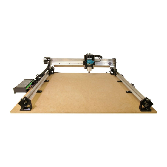
- Page 95 Machine Dimensions When getting ready to mount your LongMill, the most important dimensions you’ll need to know are the size of its foot base and the total outline of the machine. As long as your mounting surface is at least the size of the foot base and you’ve left enough space around your mounting surface to account for the total machine outline, then your setup will be suitable.
- Page 96 Generally, the sizes of each model of the LongMill have been designed to fit on the following surfaces as follows: • LongMill 12×12: Fits on a 2ft x 2ft surface • LongMill 12×30: Fits on a 2ft x 4ft surface • LongMill 30×30: Fits on a 4ft x 4ft surface The diagrams below shows a more detailed view of each of the important dimensions. Note that: 1. The red area inside the main box shows the cutting area as an offset from the foot base 2.
- Page 98 Mounting your LongMill To ensure that your machine is mounted securely and accurately, we’ve created a series of steps to help you do so. We highly recommend following these steps exactly, as the order of these steps matter. You’ll need a computer to be connected to the machine in order to align it properly.
- Page 99 Once positioned, start by moving the machine all the way to the rearmost position by jogging in the y-axis on your control software. Keep moving backwards until you hear a grinding coming from the motors on both sides; this is to confirm that your machine is all the way back and it aligns the left-side feet to the right-side feet. We’ll start by mounting the right side of the machine. Using a drill with a long Robertson driver or a short one on a bit extender works best for driving in the screws so that you have the necessary reach.
- Page 100 Alright, begin by moving the machine a couple of inches forward and mount the inside of the top and bottom feet using two wood screws (1-1/4”). Next, we’ll put screws in the other two spots on the same side, this time on the middle feet.
- Page 101 Now fasten the diagonal mounting points of all the right-side feet using the longer screws. At this point, one side of your machine will be fully secure. The technique to make sure the other side is mounted parallel to the first side is by running the gantry between its limits and mounting the other side as you move it along the length. Start by mounting the top left foot on the inside:...
- Page 102 Move the machine down so that it is roughly in the middle of it’s length, then secure the insides of the next two feet: Finally, move it to the front and secure the inside of the front left foot:...
- Page 103 Now move the machine again to the middle spot and use the longer screws to finish mounting the feet using their diagonal mounting holes. Your machine should now be fully secure to its mounting surface. From this point, you should be ready to get cutting your first jobs! If you’ve got the touch plate or the dust shoe add-ons alongside your machine, you can see our pages on how to get those assembled and set up: https://sienci.com/dmx-longmill/dust-shoes/ You can also navigate to the Post-Build section of the LongMill resources if you’d like to try out one of our easy starter projects, learn how to maintain your machine, or would like to address some issues you had during setup by visiting the page on ‘Common Issues & Fixes’...
- Page 104 Appendix: Unboxing The LongMill comes with a lot of parts, but we’ve organized them to make it as easy as possible to find and put everything together; each kit comes with several cartons. For the complete BOM, visit: https://docs.google.com/spreadsheets/d/1o4196MmMsYC8ZL_ g6McnO9MoaPllH6LNCJlDifFEhhk/edit?usp=sharing Please note that the carton layout may vary. Carton #2 is a bubble mailer.
- Page 105 Top Carton #1 Our first carton comes with stickers and a welcome letter with links to resources and safety information. If you ordered your machine with end mills or other parts, you may find them in here. Top Carton #2 Our second carton holds our steel gantries and XZ gantry assembly. Inside you will find the XZ gantry assembly and Y-axis gantries..
- Page 106 Top Carton #3 Our third carton holds several different items, including router mount and the LongMill’s controller. If you ordered your machine with any add-ons, such as the dust shoe, end mill add-on pack, or touch plate, you should find them here.
- Page 107 Top Carton #4 Our fourth carton will hold your Makita router if you ordered one. If not, it will be empty. NEMA 23 Motors Under carton #1 and #2, you will find a box containing the motors and wires.
- Page 108 Bottom Carton #1 Working our way through to the bottom cartons, our first carton holds all of the rails, lead screws, and drag chains.
- Page 109 Bottom Carton #2 In Bottom Carton #2, you will find your power supply and AC cable, USB cable, Z-axis motor mount plate, as well as bags holding all the fasteners and smaller components for your LongMill.
- Page 110 Bottom Carton #3 In our final carton, you will find all of your 3D printed parts.
Need help?
Do you have a question about the LongMill V2 and is the answer not in the manual?
Questions and answers