
Related Manuals for RTA 460ECETC-NNA1


Summary of Contents for RTA 460ECETC-NNA1
- Page 1 460ECETC-NNA1 Protocol Gateway Product User Guide Firmware Version 8.7.4 Real Time Automation, Inc. 1-800-249-1612...
- Page 2 Trademarks CompactLogix, ControlLogix, & PLC-5 are registered trademarks of Rockwell Automation, Inc. EtherNet/IP is a trademark of the ODVA. MicroLogix, RSLogix 500, and SLC are trademarks of Rockwell Automation, Inc. Microsoft, Windows, and Internet Explorer are registered ® trademarks of Microsoft Corporation. BACnet is a registered trademark of American Society of Heating, Refrigerating and Air-Conditioning Engineers (ASHRAE).
-
Page 3: Table Of Contents
Revision History ............................5 Overview ............................... 6 Hardware Platforms ............................7 Hardware – NNA1 ............................. 8 Powering the Gateway ..........................8 Mounting with a DIN Rail ..........................9 Installing ..............................9 Removing ..............................9 Accessing the Main Page..........................10 Error: Main Page Does Not Launch ......................11 Committing Changes to the Settings ...................... - Page 4 Data Mapping – Explanation ........................41 Data Mapping – Adding Diagnostic Information ..................42 String Mapping – Explanation ........................46 Mapping – Auto-Configure Mode to Manual Configure Mode ..............47 Mapping – Manual Configure Mode to Auto-Configure Mode ..............48 View as Text ..............................
-
Page 5: Revision History
Revision History Version Date Notes 8.3.9 10/21/2019 Features Added 1. Released BACnet MS/TP Slave Protocol on N2E Hardware 2. Released Profinet on N2E Hardware 3.Updated GSMDL file with new icons 4. Released S7 protocol 5. Released Wi-Fi Hardware Bug Fixes 1.Improved functionality of the Network conifguration page when going from Independent to Switch Mode. -
Page 6: Overview
Overview The 460ECETC-NNA1 gateway connects up to 32 EtherNet/IP Adapters with as many as 5 Allen-Bradley PLCs. By following this guide, you will be able to configure the 460ECETC-NNA1 gateway. For further customization and advanced use, please reference the appendices located on the CD or online at: http://www.rtautomation.com/product/460-gateway-support/. -
Page 7: Hardware Platforms
Hardware Platforms The 460 Product Line supports a number of different hardware platforms. There are differences in how they are powered, what serial settings are supported, and some diagnostic features supported (such as LEDs). For these sections, be sure to identify the hardware platform you are using. To find which hardware platform you are using: 1) Look on the front or back label of the unit for the part number. -
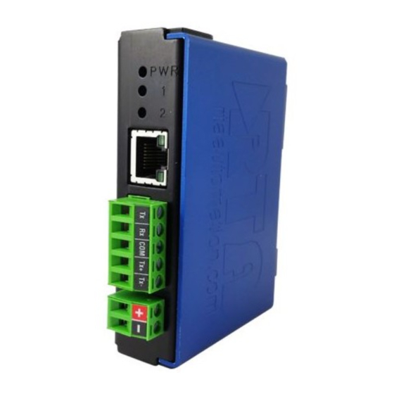
Page 8: Hardware - Nna1
Hardware – NNA1 Powering the Gateway 1) Connect a 12-24 VDC power source to the gateway, Red Wire = (+) Black Wire = (-). a) The unit draws 175mA @ 12 V. Real Time Automation, Inc. 1-800-249-1612... -
Page 9: Mounting With A Din Rail
1) Mount your DIN Rail. 2) Hook the bottom mounting flange under the DIN Rail. 3) While pressing the 460ECETC-NNA1 against the rail, press up to engage the spring loaded lower clip and rotate the unit parallel to the DIN Rail. -
Page 10: Accessing The Main Page
Accessing the Main Page The following steps will help you access the browser based configuration of the gateway. By default, DHCP is enabled. If the gateway fails to obtain an IP address over DHCP it will Auto IP with 169.254.X.Y. For more information on your Operating system network setting refer to the Access Browser Configuration Doc on the CD or download from our support web site. -
Page 11: Error: Main Page Does Not Launch
Error: Main Page Does Not Launch If the Main Page does not launch, please verify the following: 1) Check that the PC is set for a valid IP Address a. Open a MS-DOS Command Prompt b. Type “ipconfig” and press enter c. -
Page 12: Committing Changes To The Settings
Committing Changes to the Settings • All changes made to the settings of the gateway in Configuration Mode will not take effect until the gateway is restarted via the webpage. Changes will not be stored if the gateway’s power is removed prior to a reboot. -
Page 13: Main Page
Main Page The main page is where important information about your gateway and its connections are displayed. Mode (orange box below): Running Mode: Protocol communications are enabled Configuration cannot be changed during Running Mode. If changes are needed, click the Configuration Mode button shown in the green box below... -
Page 14: Device Configuration
Device Configuration The device configuration area is where you assign the device description parameter. Changes can only be made when the gateway is in Configuration Mode. Once you are done configuring the Description, click the Save Parameters button. Real Time Automation, Inc. 1-800-249-1612... -
Page 15: Network Configuration
Network Configuration The network configuration area is where you assign the IP address and other network parameters. Changes can only be made when the gateway is in Configuration Mode. Once you are done configuring the Network Settings, click the Save Parameters button. If you are changing the IP Address of the gateway, the change will not take effect until the unit has been rebooted. -
Page 16: Ethernet/Ip Scanner Configuration
EtherNet/IP Scanner Configuration Click the EIP Scanner button to access the configuration page. 1) Network Interface: Select which network you wish to communicate with EtherNet/IP scanner. If using single port hardware, the Network Interface will default to Ethernet Port only. 2) Delay Between Connect Attempts: Enter the amount of time the gateway will delay between attempts to make a connection. -
Page 17: Ethernet/Ip Scanner Device Configuration
EtherNet/IP Scanner Device Configuration The bottom area of the EtherNet/IP Scanner Configuration page lets you configure up to 32 external EtherNet/IP adapter devices. 1) To add additional adapter connections, click the -Select- dropdown under EtherNet/IP Scanner Device List and select Add Generic Adapter option. a. -
Page 18: Configuring Input Instance
Configuring Input Instance Follow these steps to manually configure the Input Instance. 1) Select View Input Instance if not already selected. 2) Run Idle Header: Check this box if the I/O adapter’s data contains information about the validity of the input data. Default value is unchecked since most devices don’t use this. 3) Request Packet Interval (RPI): This is the amount of time between each read/write request to the adapter. -
Page 19: Configuring Output Instance
Configuring Output Instance Follow these steps to manually configure the Output Instance. 1) Select View Output Instance if not already selected. 2) Run Idle Header: Check this box if the I/O adapter’s data contains information about the validity of the output data. Default value is checked since most devices use this. 3) Request Packet Interval (RPI): This is the amount of time between each read/write request to the adapter. -
Page 20: Allen-Bradley Plc Configuration
Allen-Bradley PLC Configuration Click the Allen-Bradley PLC button to access the configuration page. 1) Select which Network Interface to use for this Allen-Bradley PLC connection. If using single port hardware, the Network Interface will default to Ethernet port only. 1) Delay Between Messages: Enter the length of time to delay between read and write scan line requests (ms). -
Page 21: External Plc Configuration
External PLC Configuration The bottom area of the Allen-Bradley PLC Configuration page lets you configure up to five PLCs. There are three ways to configure this protocol: 1) Auto-Configure Group by Device (Default) 2) Auto-Configure Group by Data Type 3) Manual Mode NOTE: You may go back and forth between modes, but when reverting from Manual Mode to either of the two Auto-Configure Modes, all changes made in Manual Mode will be discarded. -
Page 22: External Plc Configuration: Auto-Configure
External PLC Configuration: Auto-Configure While in either of the two Auto-Configure modes, the number of scan lines and the actual scan lines themselves cannot be edited. Auto-Configure Mode looks at the other protocol and then configures the scan lines within the PLC to match. The PLC Tag/File Names and Data Types will be defined after the other protocol is configured. -
Page 23: Auto-Configure Group By Device Vs. Auto-Configure Group By Data Type
1) The read or write direction depends on whether it is configured as a read or write on the other protocol. 2) If the other protocol exceeds the number of Sint, Int, Dint, Real, Bool, Bit Array, or String data types the Allen-Bradley PLC supports (see limits on webpage), then nothing will be mapped. -
Page 24: External Plc Configuration: Manual Configure Mode
Group by Device - Protocol B will have 4 scan lines that will look like the following: Scan Line 1 and 2 will represent Device_1 and Scan Line 3 and 4 will represent Device_2. Scan Line 1 => Type Integer, length of 2 Scan Line 2 =>... - Page 25 PLC. This could result in message timeouts if there are a lot of devices fighting for these shared buffers. If you don’t want the RTA gateway to constantly keep the connection open to the PLC but only maintain a connection when there is data needed to be transferred, then Unconnected (UCMM) will work best if you are only writing to the PLC.
-
Page 26: Configuring Read And Write Scan Lines
It’s recommended you use Unconnected messaging so when the RTA gateway sends data to the PLC, we only send it once and close the connection until a Change of State. Leaving it at Connected messaging, once we receive data, the RTA gateway will constantly be writing to the PLC to maintain that connection. - Page 27 b) If using a Non-Logix or Micrologix PLC, below are the scan line limits. 5) Click the Save Parameters button. 6) Repeat for the other direction if needed. Real Time Automation, Inc. 1-800-249-1612...
-
Page 28: Access Program Scope Tags
Controller Scope tags, these tag names can be entered into the gateway without any additional syntax. If you are using a tag that is defined within Program Scope, then the tag name inside of the RTA gateway needs additional syntax for it to successfully communicate. -
Page 29: Optimized Trigger Guide
Optimized Trigger Guide The Optimized Trigger forces the 460ETC gateway to read ONLY the Optimized Trigger Tag until the trigger value has a change of state. Once there is a change of state then it will mark ALL ETC Read Scan Lines “Invalid”, then will execute a read for all ETC Read Scan Lines until ALL read data is valid. - Page 30 3) In the Data Mapping page, manually add 2 additional mappings identical to the example below. 4) Update all your Read Scan Line PLC tags with data. 5) Nothing should have updated in your ASCII device. 6) Update the RTA_Opt_Trigger PLC tag to 1. 7) Now your ASCII device will be updated with the data.
- Page 31 Option 2: Sends data ONLY on Change of State We’ll be using an 460ETCA for this example, this will utilize the ETC Optimization Trigger and a Write Scan Line for a handshake so that the PLC knows the triggering functionality is working. *If using the WI (Web Interface 460ETCWI) then use the WI Upload Trigger in your destination mapping* 1) Configure all your Read Scan Lines your looking to send over to your ASCII device.
- Page 32 11) Update your Read Scan Line tag with new data 12) Increment the RTA_Opt_Trigger PLC tag again 13) Now your ASCII device will be updated with the new data. 14) In a working application the Handshake tag in your PLC should match the Optimization Trigger tag. Real Time Automation, Inc.
-
Page 33: Mapping - Transferring Data Between Devices
Mapping - Transferring Data Between Devices There are 5 ways to move data from one protocol to the other. You can combine any of the following options to customize your gateway as needed. Option 1 – Data Auto-Configure Mappings: The gateway will automatically take the data type (excluding strings) from one protocol and look for the same data type defined in the other protocol. -
Page 34: Display Mapping And Values
Display Mapping and Values The Display Data and Display String pages are where you can view the actual data for each mapping that is set up. Display Data Click the Display Data button to view how the data is mapped and what the values of each mapping are. Here you will see how each data point (excluding strings) is mapped. - Page 35 This page is very useful when verifying that all data is mapped somehow from one protocol to another. If a data point is not mapped, it will display on this page in a yellow highlighted box. The Display Data page will display up to 200 mappings per page, simply navigate to the next page for the additional mapping to display.
- Page 36 To view the actual data mappings, click the Edit Mapping button. For more details, see the Data Mapping-Explanation section. To view the data mappings purely as text, click the View as Text button. For more details, see the View Data Mapping as Text section. Real Time Automation, Inc.
-
Page 37: Display String
Display String Click the Display String button to view what the values of each Parsing and/or Concatenating strings are, you can also click on the Edit Mapping to view the mapping of each string. To view the source or destination groups from a string, click the dropdown menu to generate the information regarding that device. - Page 38 If there are values of “Data Not Valid “on this page, it indicates that the source has not been validated yet and no data is being sent to the destination. NOTE: You can view the whole string data by clicking on Diagnostics Info drop down and navigating to ASCII Diagnostics page.
-
Page 39: Display String Use Case
Display String use case Sending a message of “RTA,Support,Rocks” from an ASCII device to the RTA unit. The ASCII Parsing Configuration would look like my example below. There are more detailed examples of what all the fields represent in the ASCII Parsing section. -
Page 40: Data And String Mapping - Auto-Configure
Data and String Mapping – Auto-Configure The Auto-Configure function looks at both protocols and will map the data between the two protocols as best as it can so that all data is mapped. Inputs of like data types will map to outputs of the other protocols like data types first. -
Page 41: Data Mapping - Explanation
Data Mapping – Explanation Below are the different parts that can be modified to make up a data mapping. 1) Enable (red box above): Check to enable mapping. If not checked, this mapping is skipped. 2) Source Field (yellow box above): a) Group - Select the data group you set up in the protocol config to use for this mapping. -
Page 42: Data Mapping - Adding Diagnostic Information
The gateway operates at 200 ticks per second. This equates to one tick every 5ms. Thus, mapping this to a destination will give easy confirmation of data flow without involving one of the two protocols. If data stops on the destination end, then the RTA is offline. Real Time Automation, Inc. - Page 43 4) XY_NetBmpStat a) If a protocol is a Client/Master, there is a Network Bitmap Status that is provided on the Diagnostics Info page under the Variables section. b) Since a Client/Master may be trying to communicate with multiple devices on the network, it may be beneficial to know if a Server/Slave device is down.
- Page 44 5) Status_XY a) There are two Statuses provided, one for each protocol. This gives access to the overall status of that Protocol. Each Bit has its own meaning as follows: Common Status: 0x000000FF (bit 0-7)1 byte Hex: Bit Position: Decimal: Explanation: 0x00 if we are a Slave/Server...
- Page 45 Non-Recoverable Faults 0xFF000000 (bit 24-31)4 byte Hex: Bit Position: Decimal: Explanation: 0x01 16,777,216 nonrecoverable fault – task fatal err 0x02 33,554,432 nonrecoverable fault – config missing 0x04 67,108,864 nonrecoverable fault – bad hardware port 0x08 134,217,728 nonrecoverable fault – config err 0x10 268,435,456 Configuration Mode...
-
Page 46: String Mapping - Explanation
String Mapping – Explanation Below are the different parts that can be modified to make up a string mapping. String data types can only be mapped to other string data types. There is no manipulation that can be done on the string. 1) Enable (red box above): Check to enable mapping. -
Page 47: Mapping - Auto-Configure Mode To Manual Configure Mode
Mapping – Auto-Configure Mode to Manual Configure Mode To transition from Auto-Configure Mapping Mode to Manual Configure Mode, click the dropdown at the top of the Mapping Configuration page and select Manual Configure. After you click this button, you will be prompted to confirm if this is really what you want to do. Click OK to proceed to Manual Configure Mode or click Cancel to remain in Auto-Configure Mappings Mode. -
Page 48: Mapping - Manual Configure Mode To Auto-Configure Mode
Mapping – Manual Configure Mode to Auto-Configure Mode To transition from Manual Configure Mode to Auto-Configure Mapping Mode, click the dropdown menu at the top of the Mapping Configuration page and select Auto-Configure Mappings. Click OK to proceed to delete all current mappings and go back to Auto-Configure Mappings Mode. Click Cancel to keep all mappings and remain in Manual Configure Mode. -
Page 49: View As Text
View as Text Data Mapping The View as Text page displays the point to point mapping(s) you set up in the Data Mapping section. This will also display any manipulation(s) that are configured. Each line on this page will read as follows: ->... -
Page 50: Base Triggering - Data Validiation Triggering
Note: # is an internal reference to the Server/Slave number you are settings up. ex. RTA Server/Slave products can only be Trigger 1 and Handshake 1 since we are only 1 device. If RTA is a Master/Client, then you can have a Trigger# for each server/slave connected too. - Page 51 3) Within the Data Mapping page manually add 2 additional mappings. 4) The first mapping is going to be the Data Validation Triggering. AO21 will write to the RTA, MC Trigger 1 will mark data invalid. 5) The second mapping, the MC Handshake will increment that all data is validated and write to AI21 “all data is validated”.
-
Page 52: Security Configuration
Security Configuration To setup security on the 460 gateway, navigate to Other->Security Configuration. You can configure Security for 3 administrators, 5 users, and 1 guest. THIS IS A TOTAL SECURITY FEATURE The security feature offers a way to password protect access to diagnostics and configuration on the network. -
Page 53: Security Configuration-Security Levels
Security Configuration-Security Levels Each webpage in the gateway can have a separate security level associated with it for each user. Security Levels: 1) Full Access: Capability to view and configure a web page. 2) View Access: Capability to view a web page, but cannot configure parameters. 3) No Access: No capability of viewing the web page and page will be removed from Navigation. -
Page 54: Security - Log In
Security - Log In Username: Name of the user to login. Password: Password of the user to login. Log In: If login is successful, the user will be redirected to the Main Page. Send Password to Email: Sends the specified User’s Password to the email configured for that user. Display Hint: Displays the hint specified for the User if one was set up. -
Page 55: Email Configuration
Email Configuration To setup e-mails on the 460 gateway, navigate to Other->Email Configuration. You can configure up to 10 email addresses. 1) SMTP Mail Username: The email address that the SMTP server has set up to use. 2) SMTP Mail Password: If authentication is required, enter the SMTP Server’s password (Optional). 3) SMTP Server: Enter the Name of the SMTP Server or the IP Address of the Server. -
Page 56: Alarm Configuration
Alarm Configuration To setup alarms on the 460 gateway, navigate to Other->Alarm Configuration. 1) Alarm Delay upon Powerup: At Powerup, the gateway will have values of ‘0’ stored for all data. This may cause alarms to trigger before these values are updated by the mating protocols. Set this field to provide needed time to update fields before considering values for alarms. - Page 57 5) In the Clear Error Section: a. Select the Clear Error Operation. Available options are <, >, <=, >=, !=, ==, and Change of State (COS). This is the operation that will be used to compare the Data Point value against the Error Value to determine if the alarm needs to be cleared.
-
Page 58: Diagnostics - Alarm Status
Diagnostics – Alarm Status Alarm Status will only display under the Diagnostic menu tab if at least 1 Alarm is enabled. 1) # Alarms Enabled: This is a count of enabled alarms. 2) # Alarms Active: This is how many alarms are presently active (set). 3) Last Active Alarm: This is the last alarm that the gateway detected. -
Page 59: Alarms - Clear
5) Last Active Alarm field will be populated with details on what triggered the alarm. Alarms – Clear When an alarm is cleared, the following will occur: 1) A one-time notification will be sent to the email associated with the alarm. a. -
Page 60: Change Of State (Cos) Configuration
Change of State (COS) Configuration To access the configuration files in the 460 gateway, navigate to dropdown Other->COS Configuration. The gateway, by default only writes when data has changed. The gateway also waits to write any data to the destination until the source protocol is successfully connected. Default values should fit most applications. -
Page 61: Diagnostics Info
Diagnostics Info The Diagnostics page is where you can view both protocols’ diagnostics information, # of Data Mappings, # of String Mapping and # Alarm Mappings. For protocol specific diagnostic information, refer to the next few pages. Diagnostics Mapping This section displays the number of mappings that are enabled, Data Mapping and String Mapping will show the # of Errors and First Errors. -
Page 62: Diagnostics - Ethernet/Ip Scanner
Diagnostics – EtherNet/IP Scanner Select the EtherNet/IP Scanner in the dropdown menu on the Diagnostics Page to view a breakdown of the diagnostics and common strings that are displayed on the page. You may also view individual adapter counters by selecting the device in the All Adapters dropdown and clicking View. Additional diagnostic information can be found by clicking the Help button. - Page 63 Device Status - This will only display when viewing All Adapters. 1) Connected and Running – The gateway is connected to all the EtherNet/IP adapters that are enabled and configured. 2) Connected and Idle – The gateway is connected to all the EtherNet/IP adapters that are enabled and configured but the configured outputs are not yet valid.
- Page 64 Variables - These are the values for All Adapters or the specific adapter selected. 1) Network Bitmap Status (Displayed in Hex): a) Each bit corresponds to an adapter. If the bit is set, the adapter is connected, otherwise the bit is 0.
- Page 65 Error Code Breakdown: 1) Common Allocation Error Codes - The gateway is sending an error message due to the listed explanation: 2) “Connection already in use” - The gateway tried to open a connection using the supplied parameters but failed since an existing connection was already opened. 3) “More than one guy configuring”...
-
Page 66: Diagnostics - Allen-Bradley Plc
Diagnostics – Allen-Bradley PLC Select the Allen-Bradley PLC in the dropdown menu on the Diagnostics Page to view a breakdown of the diagnostics and common strings that are displayed on the page. You may also view individual counters by selecting the device in the All PLC’s dropdown menu and clicking View. Additional diagnostic information can be found by clicking the Help button. - Page 67 LED Status - This is the Status for All PLCs or the specific PLC selected. 1) Connected (Solid Green) – All the enabled PLC devices are connected and running. 2) Not Connected (Flashing Green) – No PLCs are enabled. a) Verify Allen-Bradley PLC settings and ensure that the Enable checkbox is checked for the appropriate device(s).
- Page 68 4) Read/Write Timeouts – Since we are TCP based, the gateway will timeout on the read or write and close the TCP connection. This counter will not continually increment. The Network Bitmap Status will reflect the missing PLC. 5) Read Errors – Number of read error responses sent from the PLC to the gateway. 6) Write Requests –...
-
Page 69: Led Configuration
LED Configuration To modify the behavior of the LEDs on the 460 gateway, navigate to Other->Setup LEDs. Each LED may be set to Disabled, Protocol 1, or Protocol 2. If either protocol is a master/client, you may set the LED to represent either all slaves/servers configured in the gateway or a slave/server device. To select a slave/server device: 1) Select the protocol in the left dropdown menu. -
Page 70: Configuration Files
Configuration Files To access the configuration file in the 460 gateway, select the dropdown Other->Export/Import Config. Export Configuration The Export Configuration allows you to save your configuration file for backup or to be imported into another gateway. This file is named rta_cfg.rtax by default. Upon clicking the Save Configuration to File button, you will be prompted to select a location to save the file. - Page 71 If it encountered an error while trying to load the saved configuration, the gateway will indicate the first error it found and a brief description about it under the Load Configuration button. Contact RTA Support with a screenshot of this error to further troubleshoot.
-
Page 72: Save And Replace Configuration Using Sd Card
Save and Replace Configuration Using SD Card Saving Configuration Using SD Card This function saves the gateway’s configuration automatically to an SD Card each time the gateway is rebooted via the Restart Now button on the web page. If this unit should fail in the future, the last configuration stored on the SD card and can be used for a new gateway to get the application back up and running quickly. -
Page 73: Intelligent Reset Button
Intelligent Reset Button If the IP Address of the gateway is forgotten or is unknown, there is an easy way to recover the IP Address using a reset button on the hardware. 1) On the side of the gateway with the SD card slot, there is a small pinhole. Using a paperclip, press the button through this pinhole and hold the button for at least 5 seconds. -
Page 74: Utilities
Utilities To access the Utilities page in the 460 gateway, navigate to Other->Utilities. The Utilities screen displays information about the gateway including Operation Time, File System Usage, Memory Usage, and Memory Block Usage. Here you can also: • View the full revision of the software. •...
Need help?
Do you have a question about the 460ECETC-NNA1 and is the answer not in the manual?
Questions and answers