Advertisement
Quick Links
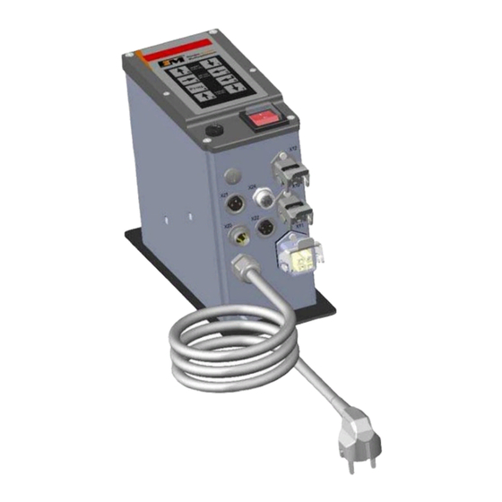
Operating instructions FS-26E
Operating instructions
Frequency control unit FS-26E
for vibratory conveyor
Art. no.: 90.0210.61
fimotec-fischer GmbH & Co. KG
Friedhofstraße 13
D -78588 Denkingen
Tel:
+49 (0)74 24 - 88 4-0
Fax:
+49 (0)74 24 - 88 4-50
E-mail:
post@fimotec.de
Internet:
www.fimotec.de
Status as of 10 / 2019
Page 1
Advertisement

Summary of Contents for fimotec-fischer FS-26E
- Page 1 Operating instructions FS-26E Operating instructions Frequency control unit FS-26E for vibratory conveyor Art. no.: 90.0210.61 fimotec-fischer GmbH & Co. KG Friedhofstraße 13 D -78588 Denkingen Tel: +49 (0)74 24 - 88 4-0 Fax: +49 (0)74 24 - 88 4-50 E-mail: post@fimotec.de...
- Page 2 In addition, you will find information as well as important warnings for your safety. Please observe: Devices of the FS-26E series are specially adapted frequency converters for the actuation of vibratory conveyors. The devices generate a mains-independent output frequency for the vibratory conveyor. An exact tuning of the vibratory conveyor is therefore not required.
- Page 3 Operating instructions FS-26E Safety-related information for the user These instructions contain the required information for the intended use of the device described herein. They are directed toward technically qualified personnel. Qualified personnel are people who have been authorized by persons responsible for the safety...
-
Page 4: Intended Use
Operating instructions FS-26E Operation The control device only functions correctly when it is correctly installed and operated. In the event of malfunctions or unclear operating states, you should check the device and remedy the malfunction (see "Error list" chapter) or have it remedied. - Page 5 Operating instructions FS-26E Application The electronic frequency converter FS 26 is used for the infinitely variable control of inductive loads, such as spiral conveyors, linear conveyors and hoppers. The device works according to the principle of pulse width modulation within the half-waves with adjustable periods of 5 - 200 Hz;...
-
Page 6: Installation
Operating instructions FS-26E Installation There are 2 bores and 2 elongated holes accessible from the outside for fastening the device. These are separated from the device interior. Important note Fasten the device to a vibration-free surface. Caution: Please make sure that the ribbon cable and control cable are not pinched against the housing in the interior. -
Page 7: Overview And Dimensions
Operating instructions FS-26E Overview and dimensions M12x1.5 Blind plug Flange socket, 2-pin, for connecting enable input (E1) – X21 Socket M12x1, 4-pin, for connecting oscillation amplitude sensor and valve output 1 (A1) – X24 Flange plug, 3-pin, for connecting status output (A5) – X23 Flange socket, 4-pin, for connecting sensor inputs (E2 + E3) –... - Page 8 Operating instructions FS-26E Connections / operating elements of control boards Status as of 10 / 2019 Page 10...
- Page 9 Operating instructions FS-26E Housing connections Vibratory conveyor connection Pin 1 - Load Pin 2 - Load Pin 3 - Not Connected - Protective conductor Mains voltage connection Pin 1 - L Pin 2 - N - Protective conductor Connection, valve output 2...
- Page 10 Operating instructions FS-26E Commissioning Before connecting the device, the mains voltage and frequency must be determined. The data must lie in the range of permissible values for the device. Check and set the jumpers according to the control type. Connect the vibratory conveyor and control cable to the control device.
-
Page 11: Control Panel
Operating instructions FS-26E Control panel The device is operated/set via 8 keys which are located on a control panel on the cover, together with a 6 x7-segment LED display. All operating mode settings as well as the settable parameters can be made via this control panel. - Page 12 Operating instructions FS-26E Keypad explanation The parameters are set by means of a menu structure and by entering an operator code. In the "Setting instructions", the menu structure and the setting ranges of the parameters, as well as the function programming, will be explained.
- Page 13 Operating instructions FS-26E Procedure example: Select level via 6 and 7 keys. Select parameter via 2 and 3 keys. Press the 4 key to get into programming mode. Enter the operator code (except for the "Amplitude" parameter), A or B.
- Page 14 Operating instructions FS-26E LEVEL 0 - Performance parameter, vibratory conveyor drive After power ON, the display switches to the "Amplitude" root display. Depending on this, the 2 and 3 keys can be used to roll to every individual parameter on this level. The following parameters are available:...
- Page 15 Operating instructions FS-26E Parameter: Soft stop [s] Code A and B Value can be set from 0.1 - 5.0 Increment 0.1 s Voltage ramp from the set amplitude value to 0V~ within the set time. Parameter: Setpoint specification [function] Code A and B...
- Page 16 Operating instructions FS-26E Parameter control selection [function] Code A and B Value can be set to 0, 1, E 0 - Drive permanently OFF 1 - Drive permanently ON E - Drive is controlled via logic level 0. Parameter parameter backup [function]...
- Page 17 Operating instructions FS-26E LEVEL d - Information output (display only) After power ON, the display switches to the "Amplitude" root display. From here, the 6 key can be used to change to level d. The following values and status displays are available: Value: Mains voltage [V~] The currently applied mains voltage is displayed.
- Page 18 Operating instructions FS-26E Display of the program version Error number is displayed. Value of applied analog voltage [V=] Value of the applied analog current [mA=] Value of the current acceleration [g] Depending on the programmed setpoint specification (parameter AE), the applied analog value is displayed here.
- Page 19 Operating instructions FS-26E LEVEL 2 - Sensor input E2 After power ON, the display switches to the "Amplitude" root display. From here, the 6 key (press 3x) can be used to change to level 2. The following parameters are available: A logical 1 causes a reaction.
- Page 20 Operating instructions FS-26E LEVEL 3 - Sensor input E3 After power ON, the display switches to the "Amplitude" root display. From here, the 6 key (press 4x) can be used to change to level 3. The following parameters are available: A logical 1 causes a reaction.
- Page 21 Operating instructions FS-26E LEVEL 0. - Logic, vibratory conveyor drive After power ON, the display switches to the "Amplitude" root display. From here, the 6 key (press 5x) can be used to change to level 0. On level 0, the control of the vibratory conveyor (physical) and the feedback of the vibratory conveyor status (logical) are defined and set.
- Page 22 Operating instructions FS-26E Parameter: Dropout delay S1 [s] Code A and B Value can be set from 0.0 - 9.9 Increment 0.1 s Depending on the physical state of the vibratory conveyor and the inversion by F2, a logical result is output.
- Page 23 Operating instructions FS-26E Parameter: Input E3 [function] Code A and B Value can be set to 0 or 1 0 - Input switched to inactive (not considered in the logic) 1 - Input switched to active (considered in the logic)
- Page 24 Operating instructions FS-26E LEVEL 1 - Transistor output logic (valves 1 + 2) After power ON, the display switches to the "Amplitude" root display. From here, the 6 key (press 6x) can be used to change to level 1. On level 1, the control of a transistor output is (physically) defined and set. The feedback is available as a further processable, immutable signal (comparable to an external control signal) with other outputs (complex control functions can be easily realized this way).
- Page 25 Operating instructions FS-26E Parameter: Input E2 [function] Code A and B Value can be set to 0 or 1 0 - Input switched to inactive (not considered in the logic) 1 - Input switched to active (considered in the logic)
- Page 26 Operating instructions FS-26E 4.10 LEVEL 5 - Relay output logic (status) After power ON, the display switches to the "Amplitude" root display. From here, the 6 key (press 7x) can be used to change to level 5. On level 5, the control of a relay output (physical) and the feedback of its status (logical) are defined and set.
- Page 27 Operating instructions FS-26E Parameter: Dropout delay S1 [s] Code A and B Value can be set from 0.0 - 9.9 Increment 0.1 s Depending on the physical state of the relay output and the inversion by F2, a logical result is output.
-
Page 28: Setting The Amplitude
Operating instructions FS-26E Parameter: Input A0 [function] Code A and B Value can be set to 0 or 1 0 - Input switched to inactive (not considered in the logic) 1 - Input switched to active (considered in the logic) - Page 29 Operating instructions FS-26E 4.12 Safely setting up the vibratory conveyor First the following connection values of the vibratory conveyor must be determined: Maximum permissible voltage [V~] Maximum permissible current consumption [A~] Operating frequency [Hz] of the used AC oscillating magnets Based on the determined values, the permissible working limits without a conveyor connected are now set (vibration amplitude 30...80 V~).
- Page 30 Operating instructions FS-26E Now set the operating frequency determined on the magnet and save. Now switch the device OFF and connect the conveyor. Switch the device back ON and go to menu item 0F again. Now the resonant frequency of the conveyor will be determined.
- Page 31 Operating instructions FS-26E 4.13 Setting up the enable/sensor input Connection, higher-level enable input E1 Pin 1 - 24V= Pin 2 - Enable input (menu: E1) (can only be actuated potential-freely) Sensor input connection E2+E3 Pin 1 - +24 V= Pin 2 - GND...
- Page 32 Operating instructions FS-26E 4.14 Factory settings / read/save user backup Via the control panel, activate the menu item 0old on level 0. Change to programming mode (see the control panel and operator code): Start in "Amplitude" root display To load the factory settings, select the menu item "re". Proceed analogously to saving.
- Page 33 Operating instructions FS-26E 4.15 Setting up external setpoint specification Connect the external setpoint to the available connection terminal on the control board via the available bore. Terminal 6 - +5 V= analogous for external potentiometer Terminal 5 - Voltage input 0-10 V=...
- Page 34 Operating instructions FS-26E 4.16 Connecting status/valve output For control tasks, there is a status relay, a 24V= transistor output, as well as a triac output (230V~) available. Connect them to the available connection sockets, depending on the application. Use a matching mating connector for this.
- Page 35 Operating instructions FS-26E Readjustment with acceleration sensor For regular operation, an acceleration sensor mounted to the vibratory conveyor is required. A supply voltage of +24V= is available. Sensors with an analog voltage output up to 6 V~ or analog current output up to 20 mA= can be connected.
- Page 36 Operating instructions FS-26E Schwingendes Teil Montageblock Sensor Schwingrichtung Festes Teil Example with linear conveyor 1. Small amplitude when mounted vertically 2. Greater amplitude when mounted at the same angle of inclination as the springs The control device and the sensor fastened to the conveyor form a closed control circuit, whereby the signal provided by the sensor has a decisive influence on the control range of the nominal value, i.e., the...
- Page 37 Operating instructions FS-26E Parameters for the control circuit on LEVEL 0 Parameter: Acceleration sensor selection Code B Value can be set to 0, U, I 0 - No acceleration sensor connected Visible after code input U - Acceleration sensor connected to voltage output I - Acceleration sensor connected to current output If a sensor type is activated, the menu for the setpoint specification is supplemented with menu item b.
- Page 38 Operating instructions FS-26E Procedure for controlling startup Mount an acceleration sensor on the drive. Connect acceleration sensor to FS 26E. POWER on Set nominal acceleration parameter 0t to 0.00. Set optimal run via frequency 0F and amplitude 0A.
-
Page 39: Technical Data
Operating instructions FS-26E Technical data Mains connection, wide 95 - 250 V~ range Output voltage ranges Automatic switching between 1 - 230 V~ 1 - 115 V~ Mains frequency 50 Hz 60 Hz Variable output frequency 5.0 - 200 Hz Output current 0.1 - 6 A~... - Page 40 Operating instructions FS-26E Setting values via keypad Parameter Delivery state Vibratory conveyor, level 0 Vibration amplitude 1...230 V~ 30 V~ Min. control limit 0A> 1...230 V~ 30 V~ Max. control limit 0A< 1...230 V~ 230 V~ Current limit 0.1...6 A~...
- Page 41 Operating instructions FS-26E Control level 1 Invert input PNP (O) PNP inverted (S) Debouncing time 0.1...99.9 ms 0.1 ms Control level 2 Invert input PNP (O) PNP inverted (S) Pick-up delay 0.0...9.9 s 0.0 s Dropout delay 0.0...9.9 s 0.0 s Debouncing time 0.1...99.9 ms...
- Page 42 Operating instructions FS-26E Logic level 5 Invert output 5.F1 Not inverted (O) Inverted (S) Invert logical state of output 5.F2 Not inverted (O) Inverted (S) Pick-up delay 5.S1 0.0...9.9 s 0.0 s Dropout delay 5.S2 0.0...9.9 s 0.0 s Logic operation...
-
Page 43: Error List
Operating instructions FS-26E Error list Danger: Life-threatening danger due to electric current! Have repairs on the 230V power network only performed by a qualified professional. Problem/error Possible cause(s) Remedy Check the Device does not work Power failure or defective fuses. - Page 44 Operating instructions FS-26E Error messages / ERROR If the complete display is flashing, an error occurred. The error code can be queried on level d under the parameter Err. The following error codes are possible: Connected acceleration sensor is defective or not connected (in regular operation only) Overload shutdown, output power exceeded, e.g., incorrect frequency...
-
Page 45: Operator Codes
CE conformity The control device FS26E is marked with the CE marking and therefore meets the relevant European directives. The company fimotec-fischer GmbH & Co. KG herewith confirms that this device meets the following directives: Low-voltage directive 2014/35/EU EMC directive 2014/30/EU ... -
Page 46: Accessories (Not Included In The Scope Of Delivery)
Operating instructions FS-26E Accessories (not included in the scope of delivery) The connection lines and oscillation amplitude sensor listed below are available as accessories: Function Length, line Slot Article number Vibration conveyor connection 1.5 m 91.4301.20 Vibration conveyor connection 91.4301.00...
Need help?
Do you have a question about the FS-26E and is the answer not in the manual?
Questions and answers