Table of Contents
Advertisement
Quick Links
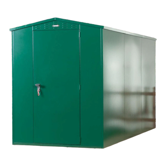
GLADIATOR PLUS 1
BASE INSTRUCTIONS
Flat and firm base. Recommended: concrete, tarmac or paving flags.
Min. distance from walls/ shrubbery: 1000mm.
Min. base size (WxDxH) 2410mm x 3790mm x 50mm.
LEVELING THE UNIT
Correctly level the constructed unit using the shims (ZCOMPPLAS)
provided prior to fixing the unit to the ground. Slide the packing pieces
under the corners of the unit base as required until an equal gap has
been achieved around the door allowing for its smooth operation and
alignment.
It is always recommended to anchor the unit to the gorund. Drill through
the four holes in each of the base of the unit using 6mm dia masonry drill
to a depth of 70mm. Screw in the anchor fixings. (These have a self
cutting thread). If not anchoring the unit, fit the self seal plugs
BEFORE BUILDING to block the fixing holes from underneath.
Please note product must be bolted down to comply with LPS1175.
TOOLS REQUIRED
Power driver POSI-DRIV screwdriver, 6mm dia. masonry drill and a
10mm socket or spanner.
For maintenance instructions of this product visit www.asgardsss.co.uk
Warning: some panels may weigh over
20Kg Beware of manual handling
Warning: Please keep
YOUR UNIQUE
this key card safe! Refer
KEY CODE
to if replacement key is
required.
x2
Advertisement
Table of Contents

Related Manuals for Asgard GLADIATOR PLUS 1


Summary of Contents for Asgard GLADIATOR PLUS 1
- Page 1 GLADIATOR PLUS 1 BASE INSTRUCTIONS Flat and firm base. Recommended: concrete, tarmac or paving flags. It is always recommended to anchor the unit to the gorund. Drill through Min. distance from walls/ shrubbery: 1000mm. the four holes in each of the base of the unit using 6mm dia masonry drill Min.
- Page 2 PLEASE NOTE ALL SCREWS ARE FIXED FROM THE INSIDE IF YOU HAVE AN OPTIONAL RAMP, PLACE UNDERNEATH FRONT BASE PANEL AT THIS STAGE...
- Page 3 PLEASE NOTE ALL SCREWS ARE FIXED FROM THE INSIDE...
- Page 4 PLEASE NOTE ALL SCREWS ARE FIXED FROM THE INSIDE...
- Page 5 PLEASE NOTE ALL SCREWS ARE FIXED FROM THE INSIDE NO SCREWS REQUIRED TOP END OF STRIP TRAPPED UNDER TOP CAP...
- Page 6 LEVEL SHED UNTIL DOORS ALIGN USING ZCOMPPLAS AS SUITABLE 54946/12.07.19/KW/REV1...
Need help?
Do you have a question about the GLADIATOR PLUS 1 and is the answer not in the manual?
Questions and answers