
Subscribe to Our Youtube Channel
Summary of Contents for LAVAL UNDERGROUND SURVEYS R-CAM 1000 XLT
- Page 1 L A V A L U N D E R G R O U N D S U R V E Y S R-CAM 1000/1300 XLT OPERATION MANUAL LAVAL UNDERGROUND SURVEYS 2476 North Bundy Drive, Fresno Ca. 93727 Phone 559-251-1396 · Fax 559-251-2096...
-
Page 2: Table Of Contents
Table of Content Operating Checklist ......................... 1 Before Starting Setup ........................1 Connecting the Camera ....................... 2 System Start Up ........................... 3 CAUTION/ATTENTION ........................4 Maintenance Instructions ....................... 5 Description of Equipment ....................... 6 Overall ............................6 Camera ............................6 Reel Assembly .......................... - Page 3 System Unpack and Check Carefully unpack the shipment and check the unit for the following: 12 Volt Battery Auxiliary Power Cable Power Cable Control Cable Battery Charger Control Unit Centering Bands (with Collars) Camera Winch Camera Case Optional Accessories (Sold Separately) See www.lavalparts.com Cable Head Repair Kit TriLight...
-
Page 4: Operating Checklist
Operating Checklist Before Starting Setup 1. Remove the 12V Battery Pack (Figure 1 Item 5) and insert the Battery Fuse and Cap into the Fuse Holder (Figure 1 Item 7) on the battery pack. 2. Connect the 12V Battery Pack to the Battery Charger and charge for a minimum of 24 hours prior to usage. -
Page 5: Connecting The Camera
Connecting the Camera 1. Turn the SPEED Dial (Figure 4 Item 4) all the way to MIN. 2. Place the REEL CONTROL Power Switch on the Control Unit in the ON position (Figure 4 Item 1). 3. Flip the Reel Control FORWARD-STOP-REVERSE Switch (Figure 4 Item 3) to the FORWARD position and turn the SPEED Dial (Figure 4 Item 4) slowly towards the MAX. -
Page 6: System Start Up
Figure 4 System Start Up 1. Position the CAM CONTROL Switch (Figure 4 Item 2) and REEL CONTROL Power Switch (Figure 4 Item 1), on the Control Unit, to ON. 2. Turn on the LCD Monitor. While watching the Monitor to verify operation Switch between side and down view and adjust light intensity, with the VIEW-LIGHT Switch (Figure 4 Item 9). -
Page 7: Caution/Attention
4. Press R on the wireless keyboard to begin recording. Press S at any time to capture a snapshot. Press ESC to stop and finalize the recording. (See Keyboard Functions Section on page 13) CAUTION/ATTENTION 1. NEVER POINT THE DOWN HOLE OR SIDE VIEW CAMERAS DIRECTLY AT THE SUN EITHER WHILE ON OR OFF 2. -
Page 8: Maintenance Instructions
16. At least ten wraps of the Cable should always be left on the Reel Assembly Cable Drum at maximum depths 17. DO NOT overtighten the cable head. Finger tighten when threading the cable head into the camera, a wrench is not necessary. Maintenance Instructions •... -
Page 9: Description Of Equipment
Description of Equipment Overall The R-Cam XLT Color Video Water Well Inspection System is equipped with two cameras in a single housing, each with a wide-angle lens, for viewing down hole and side view images in water wells or boreholes. Low light level CMOS sensors allow the cameras to detect images with minimal lighting power, as low as 1 LUX. - Page 10 Figure 5 Lower Centering Band Collar Centering Bands Thread Protector and Support Tube Upper Centering Band Collar Down View Lens Port Down View LED Lighting Port Glass Side View Lens and LED Lighting Port Camera Housing Set Screw for Centering Band Collar Screw for Centering Band...
-
Page 11: Reel Assembly
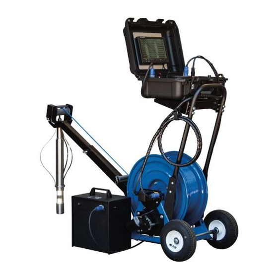
Reel Assembly A portable 12 VDC electric powered reel (Figure 6) equipped with a variable speed motor and 1,000 feet (or 1,300 feet for R-Cam 1300) of coaxial cable is used to lower or raise the Camera in the well. The coaxial cable is lightweight and Kevlar reinforced for strength. A shelf (Figure 6 Item 1) is located on the Reel Assembly to support the R-Cam Control Unit during operation. -
Page 12: Control Unit
When fully charged, the voltmeter will read about 13.0. The voltage will decrease during use. Camera functions will start to diminish when the voltmeter reads 10.0. Expected run time for the battery is 4 to 5 hours, depending on the amount of motor activity. The battery supplied with the system is AGM (Absorbed Glass Mat) Battery which uses a special absorbed electrolyte technology that is superior to conventional lead-acid batteries. - Page 13 For DVR set-up and connections, see DVR GUIDE on page 12 The VIDEO OUT (Figure 7 Item 2) is available to connect to a DVR (or Auxiliary Equipment) Video input with a BNC-RCA Cable. BNC-RCA Cables are available for purchase at www.lavalparts.com and most online retailers.
- Page 14 Figure 7 12 VDC power input connector MENU and Depth counter reset CLEAR Switch Video Signal output connection Monitor function INC/DEC Switch to external Video input 10. Reel Motor FORWARD-STOP-REVERSE Switch Monitor Power cable 11. Reel Motor SPEED Dial Reel Power connector 12.
-
Page 15: Dvr Guide
DVR Guide The Digital Video Recorder (DVR) records video and audio to USB storage media and can capture snapshot images on-the-fly without interrupting recording. It has an internal real-time clock with battery backup that provides date and time information. Videos and snapshots are saved to a folder called DCIM on the USB devices. -
Page 16: Keyboard Functions
Keyboard Functions Function Enter or Space Bar Menu or OK Up Arrow Rewind Playback or Move Text Up Down Arrow Fast Forward Playback or Move Text Down ESC (Escape) Stop/Finalize Recording, Menu Back, or Playback Stop Record Start or Pause Recording Snapshot Mute or Unmute Microphone Pause Record or Playback... -
Page 17: Play Video
Play Video Play from internal Play from external If only the internal device is present, the files list from the internal device is displayed. File selection is made using the up and down arrow keys. Pressing Enter or Space starts playback. View Snapshots Behavior is similar to “Play video”... -
Page 18: File Management
Move Up, Move Down, Move Left, Move Right Allows the text to be moved on the screen. Secondary Overlay Allows selection of Title overlay, Coded overlay, Extra overlay, or off. Setup Title/Coded/Extra Overlay Edit Text Allows the user to edit the preloaded text Load Allows the user to edit text that has been saved. -
Page 19: Setup
Setup Set Date/Time This setting allows for setting up the battery backed-up real-time clock. The real-time clock is used to automatically generate file names for saved video files and snapshots. There is also an option of having the date/time overlay present in recorded video and snapshots. Video Video Standard Allows selecting between NTSC and PAL video formats. - Page 20 Save System Parameters Saves all the parameter settings to USB memory storage. Only use this option if you wish to change the factory settings from Laval Underground Surveys. Load System Parameters Loads all the parameter settings from USB memory storage. This option restores the DVR...
-
Page 21: Helpful Dvr Tips
Turn WiFi on Setting allows streaming video over an unsecured network with a WiFi adapter when set up and turned on, for more information on how to set up please contact Laval. Helpful DVR Tips • Press ESC to stop all recordings, playbacks, and to back out of menus. Pausing a recording and powering off will erase the unfinished recording. -
Page 22: Counter Instructions
Counter Instructions In the normal operation mode after powering up the unit, the distance count is displayed on the screen along with the camera picture. The CLEAR switch (Figure 7 Item 8) clears the count to 0000.00ft (or 0000.000m). The MENU switch (Figure 7 Item 8) sequences through six on-screen modes as follows: Preset . -
Page 23: Standard Mode
Standard Mode The Standard mode allows the distance count unit of measurement to be either feet or meters. Standard INC: Feet DEC: Meters The INC switch (Figure 7 Item 9) selects the feet standard. The DEC switch (Figure 7 Item 9) selects the meters standard. NOTE: Standard Feet displayed distance is 4 whole digits with 2 decimal places (0000.00ft). -
Page 24: Status Mode
for a 5 pulse-per-revolution encoder. For a 100 pulse-per-revolution encoder a number of 400 would be entered. The INC switch (Figure 7 Item 9) increments the number by 10. The DEC switch (Figure 7 Item 9) decrements the number by 1. The CLEAR switch (Figure 7 Item 8) sets the number to 5. -
Page 25: Water Well Clarification
Particles are dislodged from the sidewalls by the passage of the camera, and the appearance on the screen or pictures is like being in a heavy snowstorm. Should you notice this occurrence contact Laval Underground Surveys regarding our line of well rehabilitation products, Boresaver. - Page 26 or common water strata shared with other wells, a particular time of the day when the other pumps are off. Sometimes you can shut off the entire field to achieve a static condition; or in an Artesian field, turn on all the other pumps to stop the muddy flow. •...
-
Page 27: Troubleshooting Guide
Troubleshooting Guide PROBLEM POSSIBLE CAUSE REMEDY 1. Rebuild Cable Head with Cable Head 1. Damaged Cable Head Repair Kit Camera not 2. Poor Cable Connections 2. Check all connecting cables working 3. Check and Correct fuse installation on properly, the battery. Test with Auxiliary Power intermittently, 3. - Page 28 1. Rebuild Cable Head with Cable Head Repair 1. Damaged Cable Head 2. Utilize Auxiliary Power Cable. Check LCD Voltmeter with Battery under load and 2. Low Battery Monitor has “No disconnected from Charger. Charge Battery 24 Signal” hours and recheck. 3.
-
Page 29: Warranty
LAVAL UNDERGROUND SURVEYS other than those set out in the immediately preceding paragraphs. All repairs shall be made by LAVAL UNDERGROUND SURVEYS at its factory or as otherwise authorized by LAVAL UNDERGROUND SURVEYS in writing. All unauthorized repairs will void warranties.
Need help?
Do you have a question about the R-CAM 1000 XLT and is the answer not in the manual?
Questions and answers