
Related Manuals for GMDE GEatom 315KTL


Summary of Contents for GMDE GEatom 315KTL
- Page 1 GMDE GEatom 315/318KTL – GEatom 315/318KTL Three-phase Grid-Tied Battery Inverter Version 1.1 Global Mainstream Dynamic Energy Technology Ltd.
-
Page 2: Table Of Contents
GMDE GEatom 315/318KTL Content Prelude ........................4 1. Safety .......................... 5 1.1 How to Use This Manual ....................5 1.2 Safety Rules ........................5 1.3 Warning Notices Affixed to the Device ................6 1.4 Important Safety Information ..................6 1.5 Disposal ........................... 8 1.6 Exclusion of Liability ...................... - Page 3 GMDE GEatom 315/318KTL 3.4.3 AC Connection ......................22 3.4.4 Communication Interface Port ................24 *3.4.5 Power Meter Installation ..................25 4. LCD Display ........................ 27 4.1 LCD Interface ......................... 27 4.2 Menu Structure ......................28 4.2.1 Main Menu ......................28 4.2.2 Energy Menu Structure ..................
-
Page 4: Prelude
The relevant up-to-date version can be obtained from www.global-mde.com Copyright The details of this documentation are the property of GMDE. Using and publicizing this documentation, even if only in parts require the written consent of GMDE. Read this user manual before you start Thank you for purchasing our products, this battery inverter is highly reliable and efficient due to its convenient design and excellent quality. -
Page 5: Safety
GMDE GEatom 315/318KTL 1. Safety 1.1 How to Use This Manual Please read the safety instructions in this manual first. Throughout the manual it is assumed that the reader is familiar with AC and DC installations and knows the rules and regulations for electrical equipment and for connecting it to the utility AC grid. -
Page 6: Warning Notices Affixed To The Device
Risk of improper handling! Personal injury by crushing, shearing, cutting, or striking. CAUTION Cancellation of the operating license! If the GMDE inverter is operated with a wrong country code, the electric supply company may cancel the operating license. CAUTION Hot Surface!... - Page 7 Check for damage to inverter and package. If you are in doubt, please contact us or the distributor before installing the inverter. Before connecting the battery packs to the inverter, check the voltages and ensure that they are within the limits of the GMDE inverter specifications. Failure to observe these specifications could void your warranty. Installation: Only trained and qualified personnel familiar with local electrical codes may work with the electrical installations.
-
Page 8: Disposal
Do not dispose the GMDE inverter with normal domestic waste. 1.6 Exclusion of Liability GMDE Technology Ltd. will not be liable for any direct, indirect or consequential damages, losses, costs or losses including without restriction any economic losses of any kind, any loss or damage to property, any personal injury, any damage or injury arising from or as a result of misuse or abuse, or the incorrect installation, integration or operation of the product. -
Page 9: Description
With GMDE GEatom series battery inverters, customers can easily retrofit existing PV system to PV energy storage system as it is shown in below Figure 1 and Figure 2. GMDE battery inverter has open interface and is capable of working with all grid-tied inverters. The energy management solutions of the energy storage systems are described as solution 1 and solution 2. -
Page 10: Description Of The Device
RS485 interface. 2.1 Description of the Device The GMDE battery inverter is a three-phase transformerless inverter, mainly being applied to charge/discharge the battery packs, which could help save client’s electricity bill by optimizing use of energy. - Page 11 ④ Integrated DC switch to switch on/off the battery. ⑤ The GMDE battery inverter provides multiple communication choice: RS485/B-USB. ⑥ 320x240 pixels display screen, on which the operation related information can be displayed. Global Mainstream Dynamic Energy Technology Ltd.
-
Page 12: Outside Dimension Of The Device
GMDE GEatom 315/318KTL 2.2 Outside Dimension of the Device Figure 4 Outside dimension of GMDE GEatom 315/318KTL 2.3 Technical Data 2.3.1 DC Data MODEL LIST GEatom 315KTL GEatom 318KTL BATTERY INPUT(DC) Operating DC Voltage Range [Vdc] 250-800 250-800 Full Power Operating Voltage Range [Vdc]... -
Page 13: Ac Data
[-0.9, 0.9] Standby Power Consumption [W] < 15 THDI (100% full power) < 3% DC current injection (Max.) [mA] Table 2 Specifications of GMDE GEatom 315/318KTL -2 2.3.3 General Data MODEL LIST GEatom 315KTL GEatom 318KTL EFFICIENCY Max. Charging/Discharging Efficiency >... -
Page 14: Installation
GMDE GEatom 315/318KTL 3. Installation 3.1 Operation Sequence Important Note before Operation To ensure the smooth operation of battery inverter and minimize the negative impact on local load in case of inverter maintenance, we strongly recommend the users to connect the battery inverter into the existing electrical system according to the following figure. -
Page 15: Unpacking
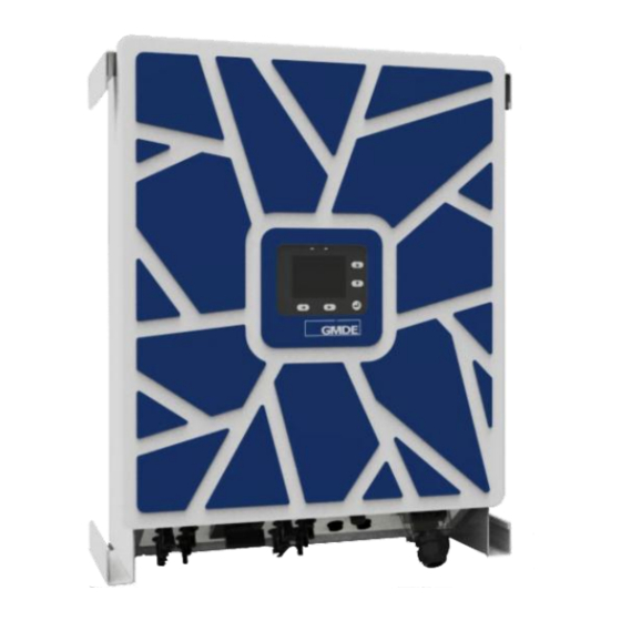
Now the battery inverter can be removed safely for maintenance. 3.2 Unpacking 3.2.1 Packing List The following items are included in the GMDE battery inverter package: 1. GMDE GEatom 315/318KTLx 1. 2. User Manual x 1. 3. Certificate of Approval x 1. - Page 16 GMDE GEatom 315/318KTL Figure 6 Front panel of GMDE GEatom 315/318KTL Global Mainstream Dynamic Energy Technology Ltd.
-
Page 17: Identifying The Inverter
GMDE GEatom 315/318KTL 3.2.3 Identifying the Inverter Global Mainstream Dynamic Energy Technology Ltd. -
Page 18: Mounting
GMDE GEatom 315/318KTL Figure 7 Label of GMDE GEatom 315/318KTL 3.3 Mounting 3.3.1 Assembly Site Requirements 1. The assembly site must be shaded so that the inverter can achieve the highest energy production and the longest life. Global Mainstream Dynamic Energy Technology Ltd. -
Page 19: Mounting The Inverter
GMDE GEatom 315/318KTL 2. The installation wall must be vertical and can carry the weight of the inverter. 3. For the assembly, it is necessary to choose a solid wall or metal construction, which comply the fire protection class F30 and the load capacity of 60kg per unit. Relevant provisions of construction regulations must be observed! 4. - Page 20 GMDE GEatom 315/318KTL Table 3 Information of GMDE GEatom 315/318KTL Mount the wall bracket by the following procedure: Mark the bracket position on the wall: hold the wall bracket to the wall, keep both sides vertical and mark screw position.
-
Page 21: Electrical Connection
Inverter wall mounting procedure 3.4 Electrical Connection 3.4.1 Connectors The GMDE inverter is provided with the following connectors, as shown below from left to right: Two pairs of battery input terminals. Integrated DC switch. Communication interface includes RS 485 A/B, USB. -
Page 22: Dc Connection
GMDE GEatom 315/318KTL 3.4.2 DC Connection DC Connection procedure includes the following steps: Please double check to ensure that the DC switch is turned off before your connection! Insert battery cables into the battery terminals. Figure 12 DC connection –battery input terminals 3.4.3 AC Connection... - Page 23 GMDE GEatom 315/318KTL Figure 14 “AC GRID” AC output terminal-aviation plug The female connector of the aviation plug has already been installed at the interface of the battery inverter. The male connector could be found in the packing box. Please find the recommended AC output cable size: Do not use cables of which losses exceed 1%.
-
Page 24: Communication Interface Port
Please refer to the following procedures of the communication connection of inverter. Figure 16 Communication connection – communication interface RS485 Configuration: GMDE inverter uses RJ45 jacks as the RS485 communication port. The RJ45 plug pin allocation is illustrated by Figure 17. Figure 17 RJ45 plug pins allocation... -
Page 25: Power Meter Installation
GMDE GEatom 315/318KTL Pin No. Illustration Data+ Data- Table 4 RJ45 plug pins illustration B-USB port: Figure 18 Insert the USB cables *Note: The B-USB port will only be used for software update. *3.4.5 Power Meter Installation (This section is only for the Integrated Energy Management Solution in section 2.1 General System... - Page 26 GMDE GEatom 315/318KTL From AC GRID Wire connection Connecting direction RS485 connection-1 RS485 connection-2 Figure 19 Wire connection of power meter Back to Top Global Mainstream Dynamic Energy Technology Ltd.
-
Page 27: Lcd Display
GMDE GEatom 315/318KTL 4. LCD Display 4.1 LCD Interface All information related to the inverter can be obtained from the LCD display. There are 5 keys for navigating in the LCD display menu. The functions of the navigating keys and indication lightings... -
Page 28: Menu Structure
GMDE GEatom 315/318KTL 4.2 Menu Structure 4.2.1 Main Menu The main menu of LCD is shown below, which is also the default window after the LCD is lighting. Figure 21 Main menu of LCD Item Description ① Operating status of the inverter ②... -
Page 29: Energy Menu Structure
GMDE GEatom 315/318KTL Figure 22 Main selection menu 4.2.2 Energy Menu Structure In the “Energy” submenu, all the historical data information can be found. By pressing “ ” on the Figure 22 main selection menu, the screen enters into “Energy” menu. -
Page 30: Run Info Menu Display
GMDE GEatom 315/318KTL Figure 23 The “Energy” menu structure 4.2.3 Run Info Menu Display The current operating status information could be found in the “Run Info” menu. By pressing “ ” on the Figure 22 main selection menu, the screen enters into “Run Info” menu as shown in Figure 24. -
Page 31: Fault & Alarm Menu Display
GMDE GEatom 315/318KTL (a) Run information on DC side (b) Run information on AC side Figure 25 “Run Info” menu structure *Note: P , current charging power; P , current discharging power; bat-c bat-d 4.2.4 Fault & Alarm Menu Display The “fault and alarm”... -
Page 32: Settings
GMDE GEatom 315/318KTL Figure 27 Menu structure of Inverter information 4.3 Settings When turning on the inverter for the first time, the customer needs to finish the following initializing settings: language setting, regulation setting, clock setting, password setting and clear data. Press “▼”... -
Page 33: Language Setting
GMDE GEatom 315/318KTL Figure 30 Main setting display 4.3.1 Language Setting Press “ ” into the default “Language” setting page. Use the navigating keys to select the language. The default language is “English”. Figure 31 Language setting Press “OK” button to finish the password input; Press “Back” button to return. -
Page 34: Password Setting
GMDE GEatom 315/318KTL Figure 32 Selecting clock setting In “Clk. Setting” window, use the navigating keys to set the local time. Figure 33 Clock setting Press “OK” button to finish the password input; Press “Back” button to return. 4.3.3 Password Setting While pressing “... -
Page 35: Battery Setting
1. In the above procedures, press “OK” button to go to the next step; Press “Back” button to return. 2. Please remember the new password if the customer changes it. Once forgetting the new password, please contact the service center of GMDE who will help you to resume the initial password. 4.3.4 Battery Setting While pressing “... - Page 36 GMDE GEatom 315/318KTL (c) Setting not successful (d) Setting successfully (e) Not supported at solution 2 (f) Not supported during the inverter running Figure 36 Battery setting After setting the parameters of the battery packs, shut down the DC switch and follow the setting &...
-
Page 37: Clear Data
GMDE GEatom 315/318KTL 4.3.5 Clear Data In this menu, all the historical data can be deleted. Please ensure that you really want to delete all the historical information before starting the following steps. On the main setting window, select “Clear Data” item and press “ ” into the “Clear Data” window. - Page 38 GMDE GEatom 315/318KTL Figure 39 Input of data deleting password After inputting the correct password, the following message box will pop up. Figure 40 Energy data deleting Press “Yes” button to delete the historical data in this page; Press “No” button to cancel.
-
Page 39: Troubleshooting
GMDE GEatom 315/318KTL 5. Troubleshooting 5.1 Safety during Troubleshooting High electric voltage! Risk of death or personal injury by electric shock! Never work with live wires! It is prior to all connection and maintenance work. Make sure that the AC and DC wires are not charged. - Page 40 GMDE GEatom 315/318KTL Warning Message Explanation Action The DC injection of grid current Acknowledge error. Contact the service if the Offset-Iac-Warning is out of range. error occurs repeatedly. Different value between master ENS-Mess-Warning Wait until the controller has re-stabilized. and slave CPU.
- Page 41 GMDE GEatom 315/318KTL Warning Message Explanation Action Bus-Start-Warning DC bus soft start is over time. Wait until the controller has re-stabilized. Bus-Low-Warning DC bus voltage is too low. Wait until the controller has re-stabilized. Bus-High-Warning DC bus voltage is too high.
- Page 42 GMDE GEatom 315/318KTL Warning Message Explanation Action External communication Check RS485 communication cable External Comm. Warning warning. connection Bat. Parameters warning Battery parameter is Zero Please set parameter of Set battery parameters before running warning. the Battery Table 7 Warnings and actions...
-
Page 43: Fault Acknowledgement
The fault can only be acknowledged after the cause of the fault has been eliminated. To acknowledge the fault messages, press the “OK” key or turn the GMDE inverter off with the DC switch. Wait for a while and turn the device on again. -
Page 44: Maintenance
GMDE GEatom 315/318KTL 6. Maintenance 6.1 Before Maintenance Please refer to “Disconnecting for maintenance” in section 3.1 Operation Sequence 6.2 Visual Inspection You should conduct visual inspection at least once a year. The visual inspection includes checking the machine cover, interface and screen. -
Page 45: Contact
If you have any questions about our product, please contact us: GMDE Room 604-605, Tongpu Road No.1220, Putuo District, Shanghai 200333, P.R. China TEL: +86 21 60710809-818 FAX: +86 21 61730300 E-mail: Service@global-mde.com WEB: www.global-mde.com SKYPE: GMDE Service Back to Top Global Mainstream Dynamic Energy Technology Ltd.
Need help?
Do you have a question about the GEatom 315KTL and is the answer not in the manual?
Questions and answers