Table of Contents
Advertisement
Quick Links
Advertisement
Table of Contents

Related Manuals for GFA 10002536 10011


Summary of Contents for GFA 10002536 10011
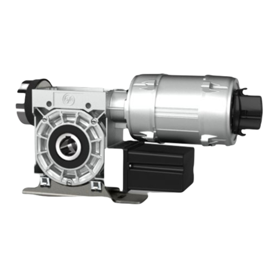
- Page 1 Pos: null /BA_Module/BA_AA Deckblatt/BAAA000001_M003 @ 17\mod_1444211755814_28.docx @ 891110 @ @ 1 Installation Instructions ELEKTROMAT SI 100.10-55,00 Model: 10002536 10011 -en- Status: 06.03.2020 Pos: null /BA_Module/BA_Seitenumbruch @ 0\mod_1190719383361_0.docx @ 550 @ @ 1...
- Page 2 Pos: null /BA_Module/BA_CA Leerblatt/BACA000001_M002 @ 15\mod_1416821436083_28.docx @ 864410 @ @ 1 GfA ELEKTROMATEN GmbH & Co. KG Wiesenstraße 81 D-40549 Düsseldorf www.gfa-elektromaten.de info@gfa-elektromaten.de Pos: null /BA_Module/BA_Seitenumbruch @ 0\mod_1190719383361_0.docx @ 550 @ @ 1...
-
Page 3: Table Of Contents
Pos: null /BA_Module/BA_DA Inhaltsverzeichnis/BADA000001_M001 @ 0\mod_1192624580455_28.docx @ 710 @ @ 1 Table of contents General safety information ....................4 Technical Data ........................ 5 Mechanical installation ....................6 Electrical installation ..................... 11 Limit switch adjustment ....................12 ... -
Page 4: General Safety Information
Pos: null /BA_Module/BA_EA Sicherheitshinweise/BAEA000003_M002 @ 4\mod_1336032695411_28.docx @ 745150 @ 1 @ 1 1 General safety information Specified normal use The drive unit is intended for doors, which have to be secured against falling down; a safety brake is included in the gearbox. The drive unit is directly mounted on the door shaft. The safe operation is only guaranteed with normal specified use. -
Page 5: Technical Data
Pos: null /BA_Module/BA_FA Technische Daten/BAFA002101_M001 @ 0\mod_1193301564087_28.docx @ 1404 @ 1 @ 1 2 Technical Data Type SG 115F Output torque 1000 Output speed Output shaft / hollow shaft 55,00 Locking torque moment 2800 Safety brake (testhouse/approval number) 14-003305-PR01 Maximum output speed open / close 18 / 18 for frequency inverter operation Supply voltage... -
Page 6: Mechanical Installation
Pos: null /BA_Module/BA_GA Mechanische Montage/BAGA004001_M001 @ 0\mod_1203410635332_28.docx @ 5259 @ 1 @ 1 3 Mechanical installation Prerequisites The permissible loads on walls, fastenings, mountings and transmission elements must not be exceeded, even for maximum holding torques or locking torques (▶ refer to technical data). - Page 7 Mounting Two elongated holes are provided for mounting (Ⓐ+Ⓑ). ▶ Vertical installation is possible only when an additional torque mount is used (Ⓑ).
- Page 8 Installation The descriptions below apply to general door specifications. The specifications of the door manufacturer must also be observed during installation. Warning - Potential injury or danger to life! During installation, be sure to use a lifting device that has a sufficient load- carrying capacity.
- Page 9 Version Ⓐ: ▶ Attach the drive unit. Version Ⓐ: ▶ Tighten all connection elements (M16) to 175 Nm. Install all other connection elements according to the specifications of the door manufacturer. Version Ⓑ: ▶ Raise the pedestal bearing (①). Install the torque mount (②+③).
- Page 10 Version Ⓑ: ▶ Attach the drive unit. Version Ⓑ: ▶ Tighten all connection elements (M16) to 175 Nm. Install all other connection elements according to the specifications of the door manufacturer. Pos: null /BA_Module/BA_Seitenumbruch @ 0\mod_1190719383361_0.docx @ 550 @ @ 1...
-
Page 11: Electrical Installation
Pos: null /BA_Module/BA_HA Elektrische Montage/BAHA030107_M001 @ 0\mod_1222150288312_28.docx @ 82818 @ 1 @ 1 4 Electrical installation Warning - Danger to life from electric current! Switch the mains OFF and check that the cables are de-energised Observe the applicable regulations and standards ... -
Page 12: Limit Switch Adjustment
Pos: null /BA_Module/BA_IA Endschaltereinstellung/BAIA101111_M001 @ 0\mod_1194954682399_28.docx @ 2518 @ 1 @ 1 5 Limit switch adjustment The adjustment of the final limit positions OPEN and CLOSE is described in the instructions for the door control panel. Pos: null /BA_Module/BA_Seitenumbruch @ 0\mod_1190719383361_0.docx @ 550 @ @ 1... -
Page 13: Motor Connection
Pos: null /BA_Module/BA_MA Motoranschluss/BAMA010003_M001 @ 0\mod_1193123387451_28.docx @ 833 @ 1 @ 1 6 Motor connection Rectifier EGR Motor X13 Motor plug Brake Pos: null /BA_Module/BA_MC Alternativer Motoranschluss/BAMC011002_M001 @ 0\mod_1271681188023_28.docx @ 518490 @ 1 @ 1 7 Alternative motor connection Rectifier EGR Motor X13 Motor plug Brake... -
Page 14: Limit Switch Connection
Pos: null /BA_Module/BA_NA Endschalteranschluss/BANA101001_M001 @ 0\mod_1193126757070_28.docx @ 963 @ 1 @ 1 8 Limit switch connection Thermal contact S10 Manual operation X12 DES connection Safety circuit Channel B (RS485) Ground Channel A (RS485) Safety circuit Supply network Pos: null /BA_Module/BA_Seitenumbruch @ 0\mod_1190719383361_0.docx @ 550 @ @ 1... -
Page 15: Emergency Manual Operation (Emergency Hand Crank)
Pos: null /BA_Module/BA_UA Nothandbetätigung/BAUA000001_M003 @ 24\mod_1511866921360_28.docx @ 1061558 @ 1 @ 1 9 Emergency manual operation (emergency hand crank) The emergency manual operation is designed for opening or closing the door without power supply. Its activation interrupts the control voltage. Electrical operation is no longer possible. Warning –... - Page 16 Plug in the crank and turn until it engages (①). Open or close by turning the crank (②). After use, the crank may be attached to the drive unit. ▶ Attach as illustrated. Pos: null /BA_Module/BA_Seitenumbruch @ 0\mod_1190719383361_0.docx @ 550 @ @ 1...
-
Page 17: Completion Of Commissioning / Testing
Pos: null /BA_Module/BA_WA Abschluss Inbetriebnahme/ Wartung/BAWA001211_M002 @ 23\mod_1511365858626_28.docx @ 1060260 @ 1 @ 1 10 Completion of commissioning / testing Check the following components and after that, mount all covers. Gearbox Check drive unit for oil loss (a few drops are not critical). Protect output shaft permanently against corrosion. - Page 18 Emergency manual operation Function to be checked in a de-energised state. Carry out functional test only between final limit positions. Limit switches Check the final limit positions by opening and closing the door completely. The safety zone must not be reached. Brake Warning –...
- Page 19 Entire drive unit Note! Have the drive checked annually by a specialist. Shorter inspection interval for frequently used doors. Observe the applicable regulations and standards. === Ende der Liste für Textmarke Inhalt ===...
-
Page 20: Declaration Of Incorporation / Declaration Of Conformity
EMC Directive 2014/30/EU within the meaning of RoHS Directive 2011/65/EU The following requirements from Appendix I of GfA ELEKTROMATEN GmbH & Co. KG the Machinery Directive 2006/42/EC are met: 1.1.2, 1.1.3, 1.1.5, 1.2.2, 1.2.3, 1.2.6, 1.3.2,...
Need help?
Do you have a question about the 10002536 10011 and is the answer not in the manual?
Questions and answers