
Related Manuals for Lemco micro line MLF-100


Summary of Contents for Lemco micro line MLF-100
- Page 2 1. IMPORTANT SAFETY PRECAUTIONS INFORMATION READ THE FOLLOWING WARNINGS BEFORE YOU USE YOUR DEVICE WARNING Παρακαλούμε φυλάξτε αυτό το εγχειρίδιο σε ασφαλές μέρος για μελλοντική αναφορά. The following safety precautions must be observed to prevent fire or electric shock hazard. Safety precautions include but are not re- stricted to the following: Power supply / Mains cord zx w Operate the unit only within the voltage range defined as appropriate by the man-...
- Page 3 Fire zx w Never place a candle or another source of fire on the unit as it may fall and start a fire. zx w If the mains cord or the power connector is damaged or destroyed, or if there is a sudden loss of picture during operation, or if you notice a strange smell or there is smoke, immediately switch the unit off, disconnect the mains cord and contact the manufacturer’s technical support department.
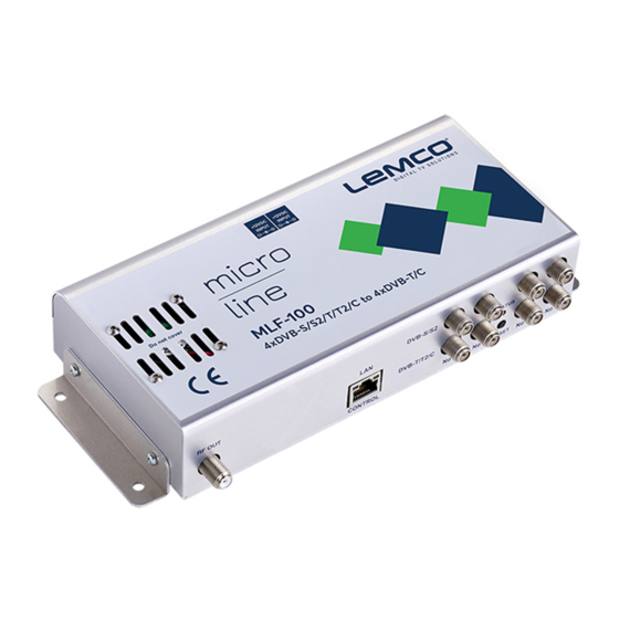
- Page 4 2. INTRO Congratulations on purchasing the MLF-100. You now own a high quality, professional DTV headend. To get the most out of your purchase, please take the time to carefully read through this manual. 3. INSTRUCTIONS 3.1 - Description The MLF-100 is a very powerful, all-in-one device, able to receive up to 4 independent satellite (DVB-S/S2), terrestrial (DVB-T/T2) or cable (DVB-C) signals and convert them in 4 x DVB-T/C RF output channels.
- Page 5 3.2.2 - “Pool” technology The MLF-100 supports “pool” technology, meaning that the user is able to select any TV or Radio program from any input and assign it to any of the 4 outputs providing great flexibility. 3.2.3 - DVB-T or DVB-C compliant The user is able to software select the modulation standard, between DVB-T and DVB- C, of the MLF-100 without the need of any firmware upgrade.
- Page 6 3.4 - Product drawing views 1. RF out 2. LAN control port 3. RF inputs 4. Power supply inputs 5. Fan cooler...
-
Page 7: Installation
4. INSTALLATION 4.1 - General The MLF-100 has a very friendly interface for programming and monitoring purposes. The user is able to gain access to the embedded webserver, by opening an Internet browser (e.g. Internet Explorer, Firefox or Chrome) and type the following static IP: 192.168.1.205. - Page 8 Outputs – Modulator 1…4 In these fields, the user is able to see the status of all the RF outputs of the device such as modulator’s state, RF output frequencies and modulation settings. System This section provides general information of the device, like internal status of all device’s mod- ules, CPU temperature and fan state as well as error codes for troubleshooting purposes.
- Page 9 Figure No3 All icons are clickable providing the ability to the user to go directly to the setup page of all internal modules of the device. The grey icons mean that the current module is disabled. Setup 4.2.4 - “Input” page In the “Input”...
- Page 10 There are four tabs, one for each input. The user is able to select the working mode of each input as follows: For Satellite signal reception the user must select DVB-S/S2 mode: 1. Tuner Enabled/Disabled - Enable or disable the specific tuner 2.
- Page 11 Figure No 5 There are 4 tabs, one for each input. Each tab depicts all the TV and Radio programs from the input that has being selected during the “Input page” processes. When the user selects one input, the device’s multiplexer does a real time analysis and depicts the program list from this specific input.
- Page 12 Figure No 6 Using the Drop-down menu from “Output” column (Figure No 7) the user is able to as- sign any program to any of the four outputs. By doing the same process for each pro- gram, from all inputs the user is able to create his own 4 custom multiplex in the output. Figure No 7...
- Page 13 Figure No 8 The status section in (Figure No 8) provides a general idea to the user of the current payload (according to the selected programs) comparing it to the max. output payload. It is recommended that the user must not exceed the 85% from each output, since all the bitrate are variable according to their specific content.
- Page 14 4.2.6 - “RF Output” page In the “RF Output” page (Figure No 9) the user is able to setup the RF output settings of the MLF-100. Figure No 9 With the use of the radio buttons the user is able to select the mode that the MLF-100 will operate as follows: DVB-T: 4 x modulator working in DVB-T standard DVB-C: 4 x modulator working in DVB-C standard...
- Page 15 * All the four outputs of the MLF-100 operate in adjacent RF output channels. This means that the user setups only the first modulator and all the other three modulators have the same settings and automatically are being programmed in adjacent channels. E.g.
- Page 16 Moreover, this section offers the ability to export / import a NIT table.. Figure No 12 For more information on how to create a custom NIT table please refer to “Lemco NIT creation guidelines.pdf” document in Lemco’s website.
- Page 17 Moreover, this section offers the ability to export / import a SDT table. Figure No 13 For more information on how to create a custom SDT table please refer to “Lemco SDT creation guidelines.pdf” document in Lemco’s website. System 4.2.10 - “Event log”...
- Page 18 Figure No 14 The user has the ability to select which kind of events to display as well as the device gives the opportunity to export these logs as follow: zx w Excel – All the program list is exported in .xlsx format zx w CSV –...
- Page 19 zx w DHCP – Enable or disable DHCP zx w IP address: Set a static IP address for controlling the device zx w Subnet mask: Set the specific Subnet mask zx w Gateway: Set the gateway’s IP address zx w Primary DNS: Set the IP address of the primary DNS zx w Secondary DNS: Set the IP address of the secondary DNS zx w Port: Assign the control port zx w MAC address: Depicts the MAC address of the LAN control...
- Page 20 4.2.13 - “System restart” page In “System restart” section (Figure No 17) the user is able to apply a full reset to the device. Figure No 17 4.2.14 - “Factory default” page In “Factory default” section (Figure No 18) the user is able to apply a factory default reset either as DVB-T or DVB-C.
- Page 21 4.2.15 - “Import/Export Config” page In “Import/Export Config” section (Figure No 19) the user is able to do the following: 1. Export: Save all the configuration is a specific file 2. Import: Upload a previously save configuration file. Figure No 19 4.2.16 - “Firmware update”...
- Page 22 4.2.17 - “Date & Time” page In “Date & Time” (Figure No 21) section the user is able to select the NTP server in order for the device to receive the date and time as well as to set the timezone of his country. Figure No 21 4.2.18 - “Info”...
- Page 23 5. TECHNICAL SPECIFICATIONS Input Specifications Input Type 4 x DVB-S/S2/T/T2/C Frequencies 950…2150 MHz DVB-S/S2 118…900MHz DVB-T/T2/C Connector 75Ω - F, female Voltage OFF / 13V / 18V Current < 400mA 22 KHz signal On / Off -Voltage 0.65V ±0.35V -Frequency 22 KHz ±4Hz -DiSEqC 1.0 (Port A, B, C, D)
- Page 24 ITU-T J.83 Standard Annex A(DVB-C), B(US cable),C Bandwidth 5, 6, 7, 8 MHz Mode Automatic modulation detection Constellation 16QAM, 32QAM, 64QAM, 128QAM, 256QAM Output Specifications DVB-T Standard EN 300-744 Bandwidth 5, 6, 7, 8 MHz Mode 2K, 8K Constellation QPSK, 16QAM, 64QAM Guard interval 1/4, 1/8, 1/16, 1/32 Code rate...
- Page 25 6. DIMENSIONS 115,18 100,50 235,00 205,00 222,00 *dimensions in mm...
- Page 26 7. LEMCO LIMITED WARRANTY This Lemco unit is guaranteed against defects in workmanship and materials for a period of five (5) years beginning on the date of purchase of the product. During the applicable warranty period, Lemco will repair or replace at our sole option, without charge, any defective component part of the purchased unit.
- Page 27 8. WARNINGS Content warning This document contains preliminary information about a product of Lemco com- pany. Lemco reserves the right to make any changes or modifications at any time without prior notice. APPENDIX A DVB-T bitrates (Mbit/s) for 8 MHz bandwidth (non-hierarchical systems)
- Page 28 DVB-T bitrates (Mbit/s) for 7 MHz bandwidth (non-hierarchical systems) Modulation Coding Rate Guard Interval 1/16 1/32 QPSK 4.354 4.838 5.123 5.278 5.806 6.451 6.830 7.037 6.532 7.257 7.684 7.917 7.257 8.064 8.538 8.797 7.620 8.467 8.965 9.237 16-QAM 8.709 9.676 10.246 10.556 11.612...
- Page 29 9. NOTES...
Need help?
Do you have a question about the micro line MLF-100 and is the answer not in the manual?
Questions and answers