
Summary of Contents for janitza Active Harmonics Filter
- Page 1 Janitza AHF Active Harmonics Filter User manual Janitza electronics GmbH Vor dem Polstück 6 D-35633 Lahnau Phone support: +49 6441 9642-22 Email: info@janitza.de www.janitza.de...
- Page 2 Information and specifications can be changed at any time. Please see our website under www.janitza.de for the current version. Janitza electronics GmbH offers their customers comprehensive technical support. Users can contact their local representative or the company's customer service center, or the head office directly, if they have any questions.
- Page 3 Janitza AHF The settings in the Parameter Settings menu are password protected (see section 8.1.3). Please cut out this section and keep it in a safe place! User password: 080808...
-
Page 4: Table Of Contents
Installation of the current transformers 5. 5. 1 Current transformer selection 5. 5. 2 CT installation on the load side (open loop) 5. 5. 3 CT installation on the grid side (closed loop) 5. 5. 4 Connection of an AHF to a Janitza UMG... - Page 5 Janitza AHF 6. Commissioning 6. 1 Before switching on the installation 6. 2 Procedure for switching on the installation 6. 3 Procedure for switching off the installation 6. 3. 1 Automatic powering on 6. 4 Emergency stop (optional) 7. Precautionary measures during maintenance 8.
-
Page 6: Information On The Device And The User Manual
Compliance with the informational products for the device is a prerequisite for safe opera- tion and attaining the stated performance characteristics and product features. Janitza electronics GmbH assumes no liability for bodily injury, material damage or finan- cial losses which result from disregard of the informational products. -
Page 7: Safety
Documentation associated with the product can be found on our website at www.janitza.de > Support > Downloads. Symbols used: This additional symbol on the device or the component itself indicates an electrical hazard that can lead to severe injury or death. -
Page 8: Safety Measures
Janitza AHF Safety measures When operating electric devices, it is unavoidable for certain parts of these devices to con- duct hazardous voltage. Consequently, severe bodily injury or material damage can occur if they are not handled properly: Electrically qualified personnel... -
Page 9: Information On Setting Up The Device
Janitza AHF Information on setting up the device • Do not set up the device in areas with high air humidity. • Keep it away from the proximity of flammable liquids, gases or explosive materials. • Ensure there is enough space in front of and behind the system for adequate ventilation and/or for maintenance work. - Page 10 Janitza AHF Standards The product complies with the following standards for safety and electromagnetic compatibility: 1. IEEE519-1992: Recommended Practices and Requirements for Harmonic Control in Electrical Power Systems; 2. GB 7251.1-2013: Low-voltage switchgear and controlgear assemblies Part 1: General rules GB/T 7251.8-2005: Low-Voltage Switchgear and Controlgear Assemblies –...
-
Page 11: Scope Of Delivery
Janitza AHF Scope of delivery Quantity Designation Active Harmonics Filter AHF part no. (14.200.XX User manual, english Cover Resistor B2508 blue 2.5 mm² Screw, 4 x 8 Resistor 1/4W -120Ω±1% Spacer washers Washers Screws 1) Part number as per delivery note... -
Page 12: Product Description
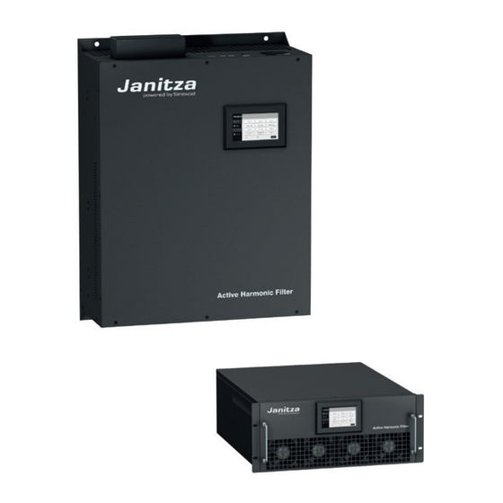
75 A/ 100 A/ 150 A 400 V - voltage R: Rack* ; W: Wall* AHF: Active Harmonics Filter Figure 2-1: Type designation example for AHF-LCD W 400V 50A * Rack – The device is mounted in a rack * Wall – The device is mounted on the wall... -
Page 13: Product Features
Janitza AHF Product features • Dynamic compensation of harmonics currents • Inductive and capacitive reactive power components • Simultaneous harmonic compensation, power factor correction and balancing of asymmetrical loads • Automatic resonance detection • Compensation of the neutral conductor current in the 4-lead connection •... -
Page 14: Dimensional Drawings
Janitza AHF Dimensional drawings Width Figure 2-2 External dimension of rack modules Width Figure 2-3 External dimension of wall modules... - Page 15 Janitza AHF Designation Width Height Depth (mm) (mm) (mm) AHF-LCD W 400 V 25 A AHF-LCD W 400 V 35 A AHF-LCD W 400 V 50 A AHF-LCD W 400 V 60 A AHF-LCD W 400 V 75 A AHF-LCD W 400 V 100 A...
-
Page 16: Operating Principle
The feedback current is fed into the power grid to compensate the harmonic current. Figure 2-4 Compensation of the harmonics current provided by the Janitza AHF... - Page 17 Janitza AHF As shown in Figure 2-5, a 3-level topology is employed in the Janitza AHF, whereby each phase branch consists of four IGBTs and two diodes. As an example, phase branch A will be considered: • When Sa1, Sa2 are switched on and Sa3, Sa4 are switched off, the voltage between point A and point O (VAO) is Vdc/2;...
-
Page 18: Installation And Power Connection
Janitza AHF Installation and power connection NOTE All AHF modules have identical current and signal interfaces. The description of the installation provided is based on the example of the filter AHF-LCD W 400 V 50 A Before installation Take note of the safety information (chapter 2)! Check the line marking of the input terminals and the line marking of the external current transformer (CT). - Page 19 Janitza AHF WARNING Risk of injury due to electrical voltage! Severe bodily injury or death can result! Therefore please abide by the following: • Switch off your installation before commencing work! Secure it against being switched on! Check to be sure it is de-energized! Ground and short circuit! Cover or block off adjacent live parts! •...
- Page 20 Post Housing plate Drilled hole All dimensions in mm Figure 3-1 Specified size and installation drawing for the Janitza AHF-LCD W 400 V 50 rack module Drilled hole Figure 3-2 Specified size and installation Drilled hole drawing for the Janitza AHF-LCD W 400 V 50...
-
Page 21: Electrical Connection
Janitza AHF Electrical connection Definition of terms: • Open Loop / Closed Loop: When connecting the converter to the AHF, a distinction is made between the two con- nection versions “open loop” and “closed loop”. • With a “retrofit” installation, the converter typically is located on the grid side (these converters are usually integrated in the feeder). -
Page 22: Open Loop
Janitza AHF If the converter is connected using the closed loop version with only one filter module, the “Network” function must be enabled when selecting the converter on the display of the AHF. Harmonics Comp Manual Grid Next Back Figure converter position 5.2.2 Open loop... -
Page 23: Electrical Connection Of An Ahf Single Module
Janitza AHF 5.2.3 Electrical connection of an AHF single module The electrical interfaces of the rack and wall modules are the same so only the electrical connection of the rack module is described here. Components for the installation of AHF-LCD R 400 V 50 A single module: •... -
Page 24: Location Of The Current And Signal Interfaces
Janitza AHF 5.2.4 Location of the current and signal interfaces Network interface and interface for potential-free contact Power terminals Signal interface PE terminal Figure 3-5 Location of the current and signal interfaces DIP switch Monitoring interface Figure 3-6 Signal interface The central 7-inch monitor is connected to the monitoring interface via the communication cable. - Page 25 Janitza AHF Table 3-1 Definition of the CT and communication signals Serial no. Marking Description CT_A Connected to S1 of phase L1 of the CT CT_A_GND Connected to S2 of phase L1 of the CT CT_B Connected to S1 of phase L2 of the CT...
- Page 26 Janitza AHF Permissible address range for the Module no. modules: Module number ≤ 8 1 (ON) 1 (ON) 1 (ON) 1 (ON) 1 (ON) 1 (ON) 1 (ON) 1 (ON) 1 (ON) Table 3-2 Description of the DIP switch and...
-
Page 27: Electrical Connection Of More Than One Module With Lcd Display
Janitza AHF Electrical connection of more than one module with LCD display When electrically connecting more than one LCD module, the interfaces for the rack and wall modules are the same, so only the connection of the rack module is described here. - Page 28 Janitza AHF Electrical connection of more than one LCD module (1~N): Grid side Load side A = L1 B = L2 C = L3 Figure 3-12 Electrical connection of two LCD modules...
-
Page 29: Electrical Connection Of Modules With Lcd Display With Different Capacities
Janitza AHF 5.3.1 Electrical connection of modules with LCD display with different capacities In the interest of satisfying different requirements for the harmonic compensation, the user may combine AHF modules with different capacity levels. For example, to compensate harmonics current and a maximum current output of 75 A, the AHF-LCD W 400 V 25 A and the AHF-LCD W 400 V 50 A can be combined with each other. -
Page 30: Electrical Connection Of Several Modules Without Display
Janitza AHF Electrical connection of several modules without display 5.4.1 Electrical connection of the AHF R 400 V 50 A AHF Figure 3-16 Electrical connection of several modules without display (1~N) Module AHF R 400 V 50 A, for example, is intended for installation in switchboard cabinets and can be monitored with a 7-inch monitor. - Page 31 Janitza AHF Signal interface of module 1 Signal interface of module 2 Signal interface of module 3 Figure 3-17 Signal interface connection for three modules...
-
Page 32: Electrical Connection Of Modules Without Display With Different Capacities
Janitza AHF 5.4.2 Electrical connection of modules without LCD display with different capacities Similar to the compensation with LCD modules, the compensation of harmonics current with different capacities is accomplished using several modules without a display. Installation is done in the same manner for these modules as for the previously described modules. -
Page 33: Installation Of The Current Transformers
Janitza AHF Installation of the current transformers Switch off your installation before commencing work! Check to be sure it is de-energized! Ground the installation! Use the ground connection points with the ground symbol to do so! Consult the documentation for the current transformers! -
Page 34: Current Transformer Selection
Janitza AHF 5.5.1 Current transformer selection The current transformer (CT) is of considerable importance in the operation with the AHF, which means that the selection of an external current transformer (CT) is very important. 3-phase conductor system without N-conductor: Two CTs are required and they must be installed on phase A (L1) and C (L3) respectively. -
Page 35: Ct Installation On The Load Side (Open Loop)
Janitza AHF 5.5.2 CT installation on the load side (open loop) After the installation of the CT on the load side, the signal is transmitted to the AHF (see Figure 3-20). In a 3-phase conductor system with an N-conductor, a CT group (3 current transformers) must be used in order to be able to detect the harmonic source. - Page 36 Janitza AHF Grid side Load side Kompensation Figure 3-21 (a) Current transformer on the load side with additional compensation Load side Grid side Kompensation Figure 3-21 (b) Current transformer on the load side with additional compensation Kompensation (Compensation before the AHF)
-
Page 37: Ct Installation On The Grid Side (Closed Loop)
Janitza AHF Kompensation 5.5.3 CT installation on the grid side (closed loop) If it is not possible to install the CT group on the load side, or if current transformers are already present on the grid side, the CT groups can also be connected on the grid side (see Kirchhoff’s law of current distribution). - Page 38 Janitza AHF Grid side Load side Kompensation Kompensation Figure 3-23 (b) Current transformer on the grid side with compensation between the transformers Grid side Load side Kompensation Kompensation Figure 3-24 Current transformer on the grid side and compensation on the load side...
- Page 39 Janitza AHF Load Figure 3-24a AHF with summation current transformer in the redundant grid...
-
Page 40: Connection Of An Ahf To A Janitza Umg
Janitza AHF 5.6.2 Connection of an AHF to a Janitza UMG Figure 3-25 Connection of an AHF to a Janitza UMG Figure 3-26 Connection of an AHF to a Janitza UMG and 7” monitor... -
Page 41: Commissioning
Janitza AHF Commissioning Before switching on the installation CAUTION Risk of injury due to electrical voltage! Severe bodily injury or death can result from: • Touching bare or stripped leads that are energized. • Inputs of the device and its components that pose a hazard when touched. -
Page 42: Procedure For Switching Off The Installation
Janitza AHF Once the device has been checked by a technician, powering on is permitted. If the system is de-energized, follow the steps for powering on shown below. Close the circuit breaker between the power grid and the AHF. Close the circuit breaker in the switchboard cabinet. -
Page 43: Automatic Powering On
Janitza AHF WARNING For maintenance or to open the switchboard cabinet, it is essential to make a measure- ment to ensure there is no voltage! 6.3.1 Automatic powering on When there is a grid disturbance or an unusual mains voltage or frequency, the AHF powers off automatically, thereby terminating the control. -
Page 44: Precautionary Measures During Maintenance
• Check the ground points regularly. • Ensure that maintenance personnel are properly trained. • Inform the Janitza service technician if the filter is used in environments with exposure to harmful oils, acids or gases. The environmental conditions must be taken into ac- count in the specific planning. -
Page 45: System Operation
Janitza AHF System operation Monitoring and troubleshooting of models with LCD 8.1.1 4.3-inch LCD screen The 4.3-inch screen on the front plate of the module makes it possible to display information on the voltage and current in realtime. It is easy to check the power status and make parameter settings. -
Page 46: The "Data" Button
Janitza AHF 8.1.2 The “Data” button • The “Data” button in the main menu takes you to the Data main menu (Figure 4-3). Figure 4-3 Data main menu Voltage • The “Voltage” button (see Figure 4-3) takes you to the “Mains voltage” menu. - Page 47 Janitza AHF Current • Select the “Current” button (Figure 4-3) and navigate to the Current main menu (Figure 4-6). Figure 4-6 Current main menu • Select “Mains current” in Figure 4-6 to check the mains current, (Figure 4-7). Figure 4-7 Display of the mains current •...
- Page 48 Janitza AHF • Select “Load Current” in Figure 4-6 to check the load current, (Figure 4-7a). Figure 4-7a Display of the load current • Select “Waveform” and “Spectrum” in Figure 4-7a to check the waveform and spectrum of the load current.
- Page 49 Janitza AHF Power • Select the “Power” button (Figure 4-3) to check the power data on the grid and load sides, including the apparent power, the active power and the reactive power, (Figure 4-10). Figure 4-10 Power analysis • Select “IO & Temp.” (Figure 4-3) to check the input/output status and the node temperature, (Figure 4-11).
-
Page 50: The "Parameters" Button
Janitza AHF 8.1.3 The “Parameters” button • The “Parameters” menu item to the left in the menu bar takes you to the Log In screen (Figure 4-12). The parameter settings are password protected. Enter the user password (see page 3) and confirm it with the Log In button. - Page 51 Janitza AHF • The System Parameters menu (Figure 4-14) offers Operating Mode, Start Mode, Transformer Position and Total Current Operating mode: There are 12 operating modes available, see below. Start Mode: “Auto”: The AHF automatically compensates the load harmonics current.
- Page 52 Parameters that are described in Figures 4-14a through Figure 4-15 are factory set and must only be changed in consultation with a Janitza service technician. • Pressing the “Next” button takes you to the menu for the compensation mode settings.
- Page 53 Janitza AHF • Pressing the “Next” button again opens the “Temperature Derating” menu. Here, if needed, the voltage upper limit and lower limit can be entered in %: Temperature Derating: On or off Capacitive Compensation: On or off Mains voltage adjustment: On or off If the mains voltage exceeds the upper limit value, the AHF feeds in inductive current.
- Page 54 Janitza AHF If a compensation rate must be set, go to the number field to the right of the word “Compensation Rate” and a screen for entry of the numbers will appear. After entry of the number, confirm with “OK” and the word “Successful” will appear on the screen.
- Page 55 Janitza AHF • The “Next” button (Figure 4-17) takes you to the “Energy Saving Function” menu. Here you can enter the times for energy saving (Figure 4-18) or select the days of the week or holidays (Figure 4-17a). Figure 4-17a Selecting holidays •...
-
Page 56: The "Measurement" Button
Janitza AHF • Close the “Parameters” main menu using the “Exit” button in the Parameters menu (Figure 4-13). Log in again with your password for every new change of the parameter settings. • The “Home” button takes you to the main menu (Figure 4-2). - Page 57 Parameters that are described in Figure 4-23 are factory set and must only be changed in consultation with a Janitza service technician. • The “Data” button to the left in the main menu allows you to access the menu for the analog addresses (Figure 4-23) via the “Test”...
- Page 58 Janitza AHF Table 4-2 Menu description for the 4.3-inch LCD screen Menu Description THDI Harmonics content of the mains current for phase A/B/C Mains current Effective value of the mains current for phase A/B/C THDI Harmonics content of the load current for phase A/B/C...
- Page 59 Displays the voltage level of the AHF, rated capacity and 3-phase 3-conductor system or 3-phase 4-conductor system Only with the optional IO module The parameters marked in gray are factory set and can only be changed in consultation with a Janitza service technician...
- Page 60 Set the harmonic compensation component; 1.0 shows 100%, etc. Target cos phi Desired cos phi Constant reactive Constant reactive power compensation is needed power The parameters marked in gray are factory set and can only be changed in consultation with a Janitza service technician...
- Page 61 Download the history of the alarm messages to a alarm download USB storage medium Save setup Message list of the actions The parameters marked in gray are factory set and can only be changed in consultation with a Janitza service technician...
-
Page 62: System Operation With More Than One Module With Display
CT0=CT1=CT2=0. Here, care should be taken to ensure that the “Total Capacity” of the two modules, Janitza AHF 25 A and Janitza AHF 50 A, be set to 75 A; the other parameter settings are the same as for when two modules with the same capacity are used. -
Page 63: Monitoring And Troubleshooting Of Modules Without Display
Janitza AHF Monitoring and troubleshooting of modules without display 8.3.1 7-inch LCD screen The 7-inch LCD screen is used for the central monitoring and troubleshooting of modules without a display. The external screen features a (800 x 400 pixel) color graphic display with a user friendly user interface. - Page 64 Janitza AHF Selecting the main menu The main menu shows the THD and effective values for all phases on the grid and load sides. A display indicates the operating status of the AHF. “Normal” – Green indicator: normal operating status "Alarm"...
-
Page 65: The "Info" Button - Realtime Information
Janitza AHF 8.3.2 The “Info” button – Realtime information "BASIC" • The button at the top right in the main menu (Figure 4-23) opens the "BASIC" menu (basic information on voltage, current, potential-free contacts, harmonics analysis and power). Information on the mains voltage, mains current, load current and compensation current can be checked (Fig. - Page 66 Janitza AHF "WAVES" • Use the “WAVES” button to go to the menu for checking the other waveforms of the grid, load and compensation current. Figure 4-29 Waves "I/O" • Use the “I/O” button in the menu bar (Figure 4-25) to query the temperatures of the phases (L1/L2/L3) and information on the potential-free contacts.
-
Page 67: The "Settings" Button
Janitza AHF 8.3.3 The “Settings” button "SYSTEM" • The “SYSTEM” button in the menu bar takes you to the Settings menu. • The parameter settings are password protected. Enter the user password (see page 3) and confirm it with Confirm. - Page 68 Janitza AHF "HARMO" • The “HARMO” button in the menu bar (Figure 4-31) takes you to the menu in which you can set the compensation rate of the 2nd to 50th harmonic. (Figure 4-32). Apply the changes with “OK”. • If the compensation function (see realtime information, Figure 4-25) is not sufficient, the parameter settings can be changed/reset via “Settings”...
- Page 69 Janitza AHF "PREFER.” • Select the “PREFER.” button in the System Settings menu (Figure 4-31). Figure 4-35 “PREFER” menu The following functions are available: • DATE: Set the current date Language: Select the monitor display language Operator Password: The parameter settings are password protected. Passwords can be changed here.
-
Page 70: The "Records" Button
Janitza AHF 8.3.4 The “Records” button • The "Records” menu item in the main menu (Figure 4-23) takes you to the alarm messages. The user can choose between active "ACTIVE" (Figure 4-36) and historical alarms - "HISTORY" (Figure 4-37) as well as select operational messages "OPERATIONS"... -
Page 71: The "Help" Button
Janitza AHF 8.3.5 The “Help” button • General instructions for troubleshooting (Figure 4-38) Figure 4-39 Troubleshooting 8.3.6 The “About” button • The “About” menu item provides information about the software version and the AHF type (Figure 4-40). Figure 4-40 Version information... -
Page 72: Menu Description
Janitza AHF 8.3.7 Menu description Table 4-3 Menu description for the 7-inch LCD screen Menu Element Description Voltage (A) Phase voltage of phase A/B/C Frequency (Hz) Voltage frequency Mains voltage THDU Harmonics content of the mains voltage for phase A/B/C... - Page 73 Janitza AHF Menu Element Description There are 12 operating modes available (mode 3 reserved) Operating modes See section 8.1.3 CT ratio Ratio of an external CT, such as 600:5 etc. - configurable CT position Either on the grid or load side, must match the current CT...
- Page 74 Janitza AHF Menu Element Description Harmonics Compensates harmonics current in the range between the current 2nd and 50th harmonic and their compensation rate Internal Set the monitoring address communication address Internal Set the transmission rate communication baud rate Comm. Internal...
-
Page 75: System Operation With More Than One Module Without Display
Janitza AHF System operation with more than one module without display For compensation of the harmonics current, a module can be operated as an individual module or be arranged in parallel with several modules. The central monitoring is accomplished using an external 7-inch LCD screen. The external 7-inch monitor is connected to the monitoring interface of one of the modules via the communication cable (Figure 4-41). - Page 76 Janitza AHF Example: • 3 modules without display - AHF R 400 V 50 A - arranged for parallel operation • Device numbers 1, 2, 3 (according to the order of their installation in the switchboard cabinet) • DIP switches set as follows: CT2=CT1=CT0=0;...
- Page 77 Janitza AHF If one switchboard cabinet is insufficient for the compensation, several systems can be combined with each other. The power supplies for the switchboard cabinets must be connected in parallel. As indicated in section 5.2, the CT interfaces must be connected to...
-
Page 78: Troubleshooting
• If the compensation appears to have little effect and there is no warning notice, contact a Janitza service technician; • If the LCD screen displays an alarm message, contact a Janitza service technician; • If the device shows no reaction on starting, contact a Janitza service technician;... -
Page 79: Appendix 1 - Part Numbers
Janitza AHF Appendix 1 – Part numbers AHF-LCD W 400 V – Wall mounted version Part number Type Version 1420020 AHF-LCD W 400 V 150 A Wall mounted & touch display 1420021 AHF-LCD W 400 V 100 A Wall mounted & touch display... -
Page 80: Appendix 2 - Technical Data
Janitza AHF Appendix 2 – Technical data AHF-LCD W 400 V – Wall mounted version Technical data Compensation current 25 A 35 A 50 A 60 A 75 A 100 A 150 A Cooling air requirement 270 m 550 m... - Page 81 Janitza AHF AHF-LCD R 400 V – Rack mounted version Technical data 150 A Compensation current 25 A 35 A 50 A 60 A 75 A 100 A Cooling air requirement 270 m 550 m 1080 m 1500 m Weight...
-
Page 82: Appendix 3 - Selection Of Cables And Accessories
200 A current CT line Less than 15 m: RVVSP 2×2.5 mm²; 15 m - 30 m: RVVSP 2×4 mm²; Over 30 m: Contact Janitza CT ratio range 150:5 to 10,000:5 Note If there are certain requirements concerning the cable temperature,... -
Page 83: Appendix 4 - Modbus Protocol
Janitza AHF Appendix 4 – Modbus protocol The Janitza AHF supports the Modbus protocol. The RS-485 interface of the AHF can accommodate connection to an external USB port or a serial interface (via a 485/USB converter or a 485/232 converter). - Page 84 Janitza electronics GmbH Vor dem Polstück 6 D-35633 Lahnau Tel.: +49 6441 - 9642-0 Email: info@janitza.de info@janitza.de | www.janitza.de...
Need help?
Do you have a question about the Active Harmonics Filter and is the answer not in the manual?
Questions and answers