Table of Contents
Advertisement
Quick Links
Advertisement
Table of Contents

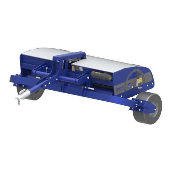
Summary of Contents for imants RotoKnife Mini
- Page 1 RotoKnife Mini Manual 998-353-0 Original document...
- Page 2 For information about settings, maintenance work or repair that this document does not cover, you are recommended to contact your supplier’s service department. This document has been produced with the greatest of care. Imants® BV cannot, however, accept any responsibility for any errors in this document or any consequences they may have.
- Page 3 . Keep the details of your type plate in a safe location. If you have any questions about your RotoKnife mini or wish to order parts, those specific details will allow us to help you quickly and efficiently.
-
Page 5: Table Of Contents
5.1 RotoKnife_Mini........................19 6 Loading and unloading the machine..................20 7 Putting the machine into operation..................21 7.1 Assembly RotoKnife mini Supported..................22 7.2 Assembly RotoKnife mini Drawn..................23 8 Transport............................. 26 9 Working with the machine......................27 9.1 Tractor settings........................28 9.2 Coupling the machine......................29 9.3 Coupling a drawn machine....................30... - Page 6 11 Cleaning............................. 44 12 Decommissioning........................45 13 Warranty.............................46 14 Appendix/Appendices......................47 15 CE declaration...........................48 Table of contents...
-
Page 7: Foreword
1 Foreword First of all, we would like to congratulate you on purchasing a Imants® machine. You have chosen a high-quality product. If used correctly, your machine will bring you many years of enjoyment. This Manual is an important document to ensure the machine is used correctly. It contains all the information required to use the machine safely and optimally. -
Page 8: Safety Instructions
2 Safety instructions The machine has been carefully designed and professionally built to allow it to be worked with safely. The CE Declaration confirms this. There are always however hazards and safety risks that cannot be excluded. The functions of the machine and its operation by the operator give rise to these hazards and risks. -
Page 9: Meanings Of Pictograms
2.1.2 Meanings of pictograms Below, you can see what the illustrations in the manual mean, what they refer to, or what they are warning you about. Danger of personal injury Fire hazard Hot surfaces Trapping risk Moving parts Leakage Explosive substances Safety footwear Hearing protection Gloves... -
Page 10: Meanings Of Operating Pictograms
2.1.3 Meanings of operating pictograms Operating pictograms indicate schematically what action must be taken or what setting must be chosen. The summary below includes all possible pictograms, which does not mean they are all used in this Manual: Hitch tension adjustment Hitch position adjustment Hitch downwards Hitch upwards... -
Page 11: General Safety Instructions
2.2 General safety instructions The user must hold a valid tractor driving licence in order to operate the machine. The user must be at least 16 years old, unless the local legislation stipulates a higher minimum age. The higher age limit shall prevail. The user of the machine is responsible at all times for compliance with local safety regulations and guidelines. - Page 12 Modifications, additions or developments on or to the machine are not allowed without the written permission of Imants BV. This includes welding on load bearing parts. Without this written authorisation, Imants BV’s responsibility for the CE marking is invalidated and is passed on to the buyer.
-
Page 13: Warning Stickers On The Machine
2.3 Warning stickers on the machine machineon page 15 for the Position of the warning stickers and type plate on the position of the warning stickers. The warning stickers below can be found on the machine. Crushing hazard. Keep hands and fingers away from the exposed, moving parts of the machine! It could cause serious physical injury with the possible loss of a hand or an arm. - Page 14 Danger of feet being cut or torn off altogether. Keep away from exposed moving parts that are part of the work process! It could cause serious injury, possibly leading to the loss of body parts. • Keep your feet away from the hazardous area while the tractor engine is running and the PTO drive shaft and/or hydraulic system are connected.
-
Page 15: Position Of The Warning Stickers And Type Plate On The Machine
2.4 Position of the warning stickers and type plate on the machine Warning labels should always be legible. The illustration below shows where the safety stickers and type plate are to be found on the machine Illustration 2: Position of the pictograms and type plate Safety instructions... -
Page 16: Operator's Responsibilities
2.5 Operator’s responsibilities It is the operator’s responsibility to ensure the machine is used safely. If the operator does not obey the safety instructions and rules, serious physical injury and major damage to the machine and the surroundings could be the result. The operator must •... -
Page 17: Residual Risks
3 Residual risks The people operating the machine are responsible for ensuring the work is carried out safely. Every machine has inherent hazards. It is therefore always recommended to exercise the greatest caution when working. Even if all the safety precautions are taken and the machine is used in accordance with the regulations, there are still residual risks: Residual risks •... -
Page 18: General Description Of Machine
4 General description of machine The machine has been designed for professional use: • On sports fields and golf courses The machine is constructed as follows: Some parts are available as an optional extra. The machine consists of a frame to which the parts listed below are attached: •... -
Page 19: Machine Specifications
5 Machine specifications 5.1 RotoKnife_Mini RotoKnife Mini Wheel set Dimensions Working width [mm] (") 1500 59.1 1500 59.1 Machine width [mm] (") 1725 67.9 2350 92.5 Machine length [mm] (") 1200 47.2 2200 86.6 Machine height (on legs) [mm] (") 37.4 18.7... -
Page 20: Loading And Unloading The Machine
6 Loading and unloading the machine Never go under a hoisted-up machine. Use only approved lifting equipment (wire ropes, belts, chains, etc.) that: • have a permissible load that is greater than the weight of the machine, see type plate • do not have any defects. -
Page 21: Putting The Machine Into Operation
7 Putting the machine into operation The user must have read through the whole contents of this manual and must follow to the letter the instructions therein. 20% of the unladen weight of the tractor must always rest on the front axle. Procedure Check: •... -
Page 22: Assembly Rotoknife Mini Supported
7.1 Assembly RotoKnife mini Supported Do not tighten the bolts of the top connection too tightly. The top connection must be able to rotate. Putting the machine into operation... -
Page 23: Assembly Rotoknife Mini Drawn
7.2 Assembly RotoKnife mini Drawn Putting the machine into operation... - Page 24 Putting the machine into operation...
- Page 25 Putting the machine into operation...
-
Page 26: Transport
8 Transport 20% of the unladen weight of the tractor must always rest on the front axle. The machine may be transported on the public road while on the tractor. Information concerning local traffic regulations must be obtained in advance. This information could include matters such as: •... -
Page 27: Working With The Machine
9 Working with the machine The operating speed must be adjusted to suit the soil and working conditions. The machine is only suitable for treating soil and fields that are free of obstacles, such as stones, tree stumps, steel objects, etc. It is not permitted to stand on the machine or to stand within the range of the machine while the machine is in use. -
Page 28: Tractor Settings
9.1 Tractor settings • Put the lifting hitch into the floating position. • Ensure there is sufficient weight at the front of the tractor • Ensure the tyre pressures are equal • Place the lifting arms at the same height. • Put the lowering speed of the hitch to slow Working with the machine... -
Page 29: Coupling The Machine
9.2 Coupling the machine In order to use the machine it must first be coupled up Set the tractor lift arms at equal height During all operational activities, make sure the machine cannot roll away unintentionally. Send people away from the danger area between the tractor and the machine Drive the tractor close to the machine, leaving about 25 cm of room between the tractor and the machine Secure the tractor to prevent unintended starting or rolling away... -
Page 30: Coupling A Drawn Machine
9.3 Coupling a drawn machine In order to use the machine it must first be coupled up During all operational activities, make sure the machine cannot roll away unintentionally. Send people away from the danger area between the tractor and the machine Drive the tractor close to the machine, leaving about 25 cm of room between the tractor and the machine Secure the tractor to prevent unintended starting or rolling away... -
Page 31: Machine Settings
Before carrying out maintenance work or changing the machine’s settings, it must have come to a complete standstill. The tractor’s engine must be switched off and the key must have been removed from the ignition. For reasons of quality and safety, only use original Imants® parts. Procedure Illustration ... - Page 32 Procedure Illustration Minidisc surface aeration: Cut at a minimum depth in hard and dry ground conditions Table 4: CarouselR15 Procedure Illustration Minidisc intense surface aeration: Shallow slitting of greens and cutting loose thatch Table 5: CarouselR29 Working with the machine...
- Page 33 Procedure Illustration Raise the machine Lock the handle in position. Both sides. Rotate the carousel to the desired position. Lock the handle in position. Both sides. Table 6: Locking Working with the machine...
-
Page 34: Ballast
Before carrying out maintenance work or changing the machine’s settings, it must have come to a complete standstill. The tractor’s engine must be switched off and the key must have been removed from the ignition. For reasons of quality and safety, only use original Imants® parts. Procedure Illustration Remove the cover. -
Page 35: Starting And Stopping Work And Settings
9.5 Starting and stopping work and settings Working with the machine is described in the two tables below. Actions that recur during every job for starting and stopping are shown printed in bold. One-off settings are printed normally. Some of the instructions may concern an optional extra that your machine may not have. Adjust carousel Carouselon page 31 Drive forwards. -
Page 36: Uncoupling The Machine
9.6 Uncoupling the machine Be aware of residual mechanical, hydraulic, pneumatic and electrical energy present in the machine. Put the carousel into transport position Place the machine on a flat, stable surface During all operational activities, make sure the machine cannot roll away unintentionally. Secure the tractor to prevent unintended starting or rolling away Disengage the three-point hitch Drive the tractor forward about 25 cm... -
Page 37: Uncoupling A Drawn Machine
9.7 Uncoupling a drawn machine Put the carousel into transport position Place the machine on a flat, stable surface During all operational activities, make sure the machine cannot roll away unintentionally. Secure the tractor to prevent unintended starting or rolling away Drive the tractor forward about 25 cm Working with the machine... -
Page 38: Maintenance Of The Machine
Be aware of residual mechanical, hydraulic, pneumatic and electrical energy present in the machine. Work may only be carried out under a raised machine if the machine has been properly supported. For reasons of quality and safety, only use original Imants® parts. 10.1 Daily inspection General Guards •... -
Page 39: Wear Parts
The tractor’s engine must be switched off and the key must have been removed from the ignition. For reasons of quality and safety, only use original Imants® parts. Dispose of any worn components in an environmentally responsible manner. Always follow the locally applicable statutory regulations. -
Page 40: Replacing The Spiker R14 Discs
10.2.2 Replacing the spiker R14 discs For reasons of quality and safety, only use original Imants® parts. Before carrying out maintenance work or changing the machine’s settings, it must have come to a complete standstill. The tractor’s engine must be switched off and the key must have been removed from the ignition. - Page 41 Maintenance of the machine...
-
Page 42: Replacing The Spiker R15 Discs
10.2.3 Replacing the spiker R15 discs For reasons of quality and safety, only use original Imants® parts. Before carrying out maintenance work or changing the machine’s settings, it must have come to a complete standstill. The tractor’s engine must be switched off and the key must have been removed from the ignition. - Page 43 Maintenance of the machine...
-
Page 44: Cleaning
11 Cleaning Carefully check hydraulic hoses and electrical cables. Never treat hydraulic hoses and electric cables with gasoline, benzene, petroleum or mineral oils. Lubricate the machine after cleaning it. Especially after the machine has been cleaned using a high-pressure cleaner/steamer or fat-soluble agents. Observe the legal requirements concerning the use and disposal of cleaning agents. -
Page 45: Decommissioning
12 Decommissioning When the machine is decommissioned, the parts can be sorted as follows: Metals Plastics Oils and greases Dispose of the sorted materials in an environmentally responsible manner. Always follow the locally applicable statutory regulations. Decommissioning... -
Page 46: Warranty
Motors and all accessories that are delivered with products from IMANTS BV but which are not manufactured by IMANTS BV are not covered by the warranty issued by IMANTS BV. They are only sold with the explicit warranty, if there is one, issued by the manufacturer concerned. -
Page 47: Appendix/Appendices
14 Appendix/Appendices In this part of the manual, you can find extra information about your machine Appendix/Appendices... -
Page 48: Ce Declaration
15 CE declaration CE declaration... - Page 49 16 Notitieblad/Note sheet/Notizenblatt Notitieblad/Note sheet/Notizenblatt...
- Page 50 17 Notitieblad/Note sheet/Notizenblatt Notitieblad/Note sheet/Notizenblatt...
- Page 51 18 Notitieblad/Note sheet/Notizenblatt Notitieblad/Note sheet/Notizenblatt...
- Page 52 Imants ® Turnhoutseweg 29 5541 NV Reusel +31 (0)497 642 433 +31 (0)497 643 205 www.imants.nl info@imants.nl...
Need help?
Do you have a question about the RotoKnife Mini and is the answer not in the manual?
Questions and answers