
Related Manuals for ComNav V4

Summary of Contents for ComNav V4
- Page 1 HERMAL AND ULTRA LOW LIGHT CAMERA SYSTEM Installation & Operation Manual PN 11610037 V1.0...
-
Page 3: Welcome
Congratulations on your purchase of ComNav Marine Ltd. V4 Camera System. At ComNav Marine Ltd., we are dedicated to reliability & quality in all our products, and the V4 camera system is a good example of that. We promise to do our best to ensure your satisfaction with your new V4 Camera System. - Page 4 ComNav V4 Installation & Operation There are various versions of this thermal camera system that are approved for international distribution without the export control restrictions. Please contact ComNav Marine Ltd. if you have any questions. ComNav Marine Ltd. #15 - 13511 Crestwood Place...
-
Page 5: Document History
ComNav V4 Installation & Operation Document History Revision Description first release Document PN 11610037 V1.0 - 3 -... -
Page 6: About This Manual
This manual provides essential information for the safe and reliable operation of the ComNav V4 Camera System. Read this manual in its entirety before using the Camera System for the first time. Keep the manual handy until you become thoroughly familiar with the operation of the camera system. -
Page 7: Table Of Contents
ComNav V4 Installation & Operation Table of Contents Welcome ___________________________________________________________________________ 1 Warranty Notice ................................. 1 General Notice ................................1 Proprietary ................................. 1 Copyright ................................... 1 Special Note ................................1 Document History ..............................3 About this Manual ..............................4 Manual Format ................................4 Table of Contents ___________________________________________________________________ 5 List of Figures ................................ - Page 8 ComNav V4 Installation & Operation Care & Maintenance ________________________________________________________________ 33 Warning ..................................33 Protection of Wires and Cabling ..........................33 Periodic Checks ............................... 33 General Precautions..............................33 Repair ..................................33 Fuse Replacement ..............................33 Cleaning ................................... 34 UPS and CPU Batteries ............................34 Appendix 1 ________________________________________________________________________ 37 Specifications ................................
-
Page 9: List Of Figures
Figure 12 – Photosensor tab options........................... 28 Figure 13 – Gyroscope tab settings............................. 29 Figure 14 – Mechanical Drawing Specification........................40 Figure 15 – Wiring of the V4 Camera..........................41 List of Tables Table 1 – V4 Camera Box Content............................10 Table 2 –... - Page 10 ComNav V4 Installation & Operation Introduction Document PN 11610037 V1.0 - 8 -...
- Page 11 ComNav V4 Installation & Operation Document PN 11610037 V1.0 - 9 -...
-
Page 12: When You Open The Box
Contact your supplier immediately if any of the parts listed below are missing or damaged Camera Package Contents Item Part # Description Quantity 11610037 V4 Camera and Joystick Controller 29010109 Installation / Operating Manual Table 1 – V4 Camera Box Content. Document PN 11610037 V1.0 - 10 -... -
Page 13: Safety Notes
The camera and accessories are referred to as ‘Camera system’ hereafter in this document. The V4 Imaging camera is designed to be used in conjunction with other navigational aids and should not be used as the sole or primary navigation device. - Page 14 ComNav V4 Installation & Operation Introduction Document PN 11610037 V1.0 - 12 -...
-
Page 15: System Introduction
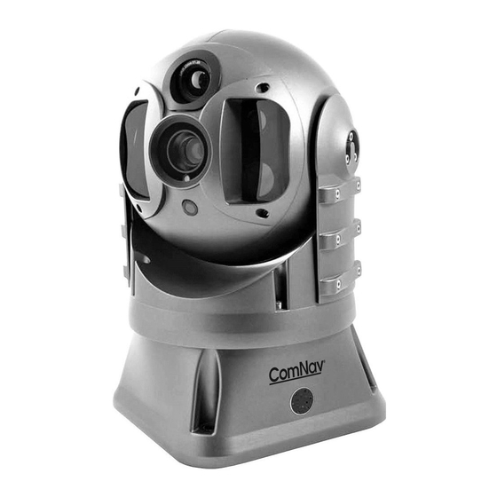
Figure 1 – Various Camera Systems Setup. V4 Camera System The V4 camera is equipped with two cameras, an ultra-sensitive thermal camera and an ultra low light day camera, that are specifically designed for marine applications. Unlike conventional cameras, thermal Imaging cameras sense heat in the form of Infra Red (IR) radiation given off by objects rather than amplifying ambient light. -
Page 16: Joystick/Keypad Controller
ComNav V4 Installation & Operation Introduction Joystick/Keypad Controller The Figure 2 shows the Joystick/Keypad controller which is the control unit of the V4 camera system. It allows full access and control of all the camera’s features and menu setup. Figure 2 – Joystick/Keypad Controller. - Page 17 ComNav V4 Installation & Operation Introduction Document PN 11610037 V1.0 - 15 -...
- Page 18 ComNav V4 Installation & Operation Operation Document PN 11610037 V1.0 - 16 -...
- Page 19 ComNav V4 Installation & Operation Document PN 11610037 V1.0 - 17 -...
-
Page 20: Operation
ComNav V4 Installation & Operation Operation The Figure 3 shows the Joystick controller along with a description of the buttons functions. Screenshot Power Button Button Function Button Reset/Home (for Images) Button Status/Alarm Joystick Failure Zoom In/Out Day/Night mode Brightness level... -
Page 21: On Screen Display Symbols
ComNav V4 Installation & Operation On Screen Display Symbols Clicking the power button will display the Startup Screen shown in Figure 4, where the Left (shown in Blue) portion displays the video feed while the right section shows different settings and relevant scene information and icons. -
Page 22: Picture In Picture (Pip) Icon
ComNav V4 Installation & Operation Picture In Picture (PIP) ICON Click the PIP ICON to activate the dual cameras (visible light camera and thermal camera). Click the icon once again to deactivate the dual mode cameras and return to the single mode camera. -
Page 23: Functions Icon
ComNav V4 Installation & Operation Functions ICON Click to show the special functions menu. The menu shows the different slaving options (radar and gyrocompass) as well as the video-tracking and gyro-stabilization options. Video Adjustment ICON Click on Icon to adjust the visible light camera video settings. The menu allows adjusting the brightness, colour saturation, contrast, enable/disable greysacle vision and invert colours. -
Page 24: Telemetery/Diagnose/Settings Icon
ComNav V4 Installation & Operation Figure 6 – Battery Status. Telemetery/diagnose/settings ICON Click to show the Telemetry menu. Requires password to modify camera settings. Thermal Camera menu The following icons represents the Thermal camera icon submenu options. White Hot ICON Show Hot objects in the scene in WHITE. -
Page 25: Gain+ Icon
ComNav V4 Installation & Operation Gain+ ICON Click to increase the scene contrast. Gain- ICON Click to decrease the scene contrast. Restore Default Parameter ICON Click on Icon to restore default parameters. LUM+ ICON Click to increase luminosity. LUM- ICON Click to decrease luminosity. -
Page 26: Colour Palette
ComNav V4 Installation & Operation Colour Palette Sets the colour palette. Opens the palette shown in Figure 7. Figure 7 – Colour palette menu options. Zoom Feature The Figure 8 shows that the Ultra Low Lux Colour camera is active (indicated by the green circle in the visible daylight camera ICON), and the Zoom is active (Indicated in the top left hand corner of Figure 8 by “Optical Zoom... -
Page 27: Figure 8 - Colour Camera Zoom Feature
ComNav V4 Installation & Operation Figure 8 – Colour Camera Zoom Feature. The Figure 9 shows that the Thermal camera is active (indicated by the green circle in the Thermal camera ICON), and the Zoom is active (Indicated in the top left hand corner of Figure 9 by “Zoom X1.0”). The zoom can be further increased/decreased by rotating the knob of the Joystick in Figure 3 clockwise/counter-clockwise respectively. -
Page 28: Figure 9 - Thermal Camera Zoom Feature
ComNav V4 Installation & Operation Figure 9 - Thermal Camera Zoom feature. Document PN 11610037 V1.0 - 26 -... -
Page 29: The Telemetry/Diagnose/Setting
ComNav V4 Installation & Operation The Telemetry/Diagnose/setting The Figure 10 shows the Telemetry Panel Settings having six tabs: System, Keyboard, Motor, Photosensor, Gyroscope and Configuration. A description of each of the tabs is as follows: System Tab shows the system status. -
Page 30: Figure 11 - Motor Tab Options
ComNav V4 Installation & Operation Figure 11 – Motor tab options. Figure 12 – Photosensor tab options. Document PN 11610037 V1.0 - 28 -... -
Page 31: Figure 13 - Gyroscope Tab Settings
ComNav V4 Installation & Operation Figure 13 – Gyroscope tab settings. Document PN 11610037 V1.0 - 29 -... - Page 32 ComNav V4 Installation & Operation Document PN 11610037 V1.0 - 30 -...
- Page 33 ComNav V4 Installation & Operation Care & Maintenance Document PN 11610037 V1.0 - 31 -...
- Page 34 ComNav V4 Installation & Operation Document PN 11610037 V1.0 - 32 -...
-
Page 35: Care & Maintenance
ComNav V4 Installation & Operation Care & Maintenance The V4 Camera System has been designed to provide many years of reliable service. The following care and maintenance tips will help to ensure the longevity of the equipment. Warning Do not rotate the sensor using your hand. -
Page 36: Cleaning
ComNav V4 Installation & Operation Cleaning Clean the camera window only with low-pressure fresh water and a soft cloth. For water spots, wipe the lens cover with a clean, fresh water dampened lens cloth. UPS and CPU Batteries UPS batteries must be replaced every two years, while Control CPU batteries must be replaced every four years. - Page 37 ComNav V4 Installation & Operation Appendices Document PN 11610037 V1.0 - 35 -...
- Page 38 ComNav V4 Installation & Operation Document PN 11610037 V1.0 - 36 -...
-
Page 39: Specifications
ComNav V4 Installation & Operation Technical Information Appendix 1 Specifications Thermal Camera Parameter Specification Dual Payload Thermal, Lowlight & Daylight Pack w/Joystick Controller (30 mm Lens, 100 Hz) Description Field of View horizontal, 19 Vertical (@ wide zoom) (FOV) Sensor Silicon CMOS Uncooled Microbolometer Chip 640 x 480 –... -
Page 40: Ultra-Low Lux Camera
ComNav V4 Installation & Operation Technical Information Ultra-Low Lux Camera Parameter Specification Number of Cameras Type Ultra-Low Lux Colour Camera Sensitivity 0.01 Lux @ Colour ° ° Field of View (FOV) x 30 (@ wide zoom) Sensor SuperChip II SSNR III Starlight... -
Page 41: Mechanical
ComNav V4 Installation & Operation Technical Information Mechanical Parameter Specification Camera Dimension 180 x 180 x 310 mm Camera Weight 4.9 kg Jostick Keypad 16 cm x 12 cm Dimension 6.1in x 4.5 in Enclosure Rating IP 68 Metallic – High Strength Aluminium Alloy... -
Page 42: Mechanical Specifications
ComNav V4 Installation & Operation Technical Information Appendix 2 Mechanical Specifications The Figure 14 shows the dimensions of the V4 Camera. It is advisable to mount the camera on a shock absorber. Figure 14 – Mechanical Drawing Specification. Document PN 11610037 V1.0... -
Page 43: Installation
Technical Information Appendix 3 Installation The Figure 15 shows the wiring connections of the V4 camera, Joystick, and touch monitor to the control box and to the power supply. Figure 15 – Wiring of the V4 Camera. Document PN 11610037 V1.0... -
Page 44: Ordering Information
ComNav V4 Installation & Operation Ordering Appendix 4 Ordering Information Part # V4 GYRO STABILIZED CAMERA 11610037 V4 Dual Payload Thermal, & Low-light Pack w/Joystick Controller (30 mm Lens, 100 Hz) V4 ACCESSORIES 31610068 30FT Extension Video Cable 21610033 Second Station Joystick Controller 21610034... -
Page 45: Troubleshooting
ComNav V4 Installation & Operation Troubleshooting Appendix 5 Troubleshooting Unresponsive Video Output If the video output is too slow or corrupted, Press the power button on the Joystick to turn off the system. If the problem is not resolved by the prior step, Press the power button once again on the... -
Page 46: Warranty Information
ComNav does not warrant or guarantee that the Equipment will perform in accordance with the requirements of such usage; 2. ComNav reserves the right to modify the Equipment without any obligation to notify, supply or install any improvements or alterations to existing Equipment. - Page 47 The Limited Warranty will not apply with respect to any defective Equipment unless written notice of such defect is given to ComNav, by mail to the address for ComNav set forth below, or by facsimile to ComNav at 604-207-8008, and unless that written notice is received by ComNav within ten (10) days of the date upon which the defect first became known to the Purchaser.
- Page 48 ComNav is unable to remedy the defect after having a reasonable number of opportunities to do so. 4. Warranty service shall be performed only by ComNav. Any attempts to remedy the defect by anyone else shall render the warranties set forth in this Warranty null and void.
- Page 49 ComNav V4 Installation & Operation Warranty Document PN 11610037 V1.0 - 47 -...
- Page 50 ComNav V4 Installation & Operation User Notes User Notes Document PN 11610037 V1.0 - 48 -...
-
Page 51: User Notes
ComNav V4 Installation & Operation User Notes User Notes Document PN 11610037 V1.0 - 49 -...
Need help?
Do you have a question about the V4 and is the answer not in the manual?
Questions and answers