Table of Contents
Advertisement
Advertisement
Table of Contents

Subscribe to Our Youtube Channel
Related Manuals for Viper Viper 600.1

Summary of Contents for Viper Viper 600.1
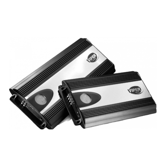
- Page 1 d600.1 model d1200.1...
- Page 2 © 2002 Directed Electronics, Inc...
-
Page 3: Table Of Contents
CONGRATULATIONS Congratulations for choosing a Viper Audio power amplifier from Directed Electronics, the industry leader in high quality automotive security and audio equipment since 1990. With the introduction of Viper Audio power amplifiers, Directed Electronics continues to set new standards of performance, reliability, and affordability in the mobile electronics industry. -
Page 4: Limited Two-Year Consumer Warranty
LIMITED TWO-YEAR CONSUMER WARRANTY Directed Electronics, Inc. promises to the original purchaser, to replace this product should it prove to be defective in workman- ship or material under normal use, for a period of two years from the date of purchase by the dealer as indicated by the date code marking of the product PROVIDED the product was installed by an... -
Page 5: Features
FEATURES Super-efficient Class D PWM design runs much cooler than conventional amps. High-speed MOSFET switching power supply. High-current complimentary MOSFET outputs stable into 1 ohm loads. Thermal, DC offset, reverse polarity, and short circuit protection with status LED. Master/slave RCA jack functions support two amps bridged to one load. -
Page 6: Installation Guidelines
INSTALLATION GUIDELINES 1. Please read this owner’s manual carefully before installing this ampli- fier. 2. Disconnect the battery ground terminal prior to making any elec- trical connections. 3. Check for any hazards or obstruc- tions such as gas tanks, fuel or brake lines, and wiring harnesses before mounting the amplifier. -
Page 7: Wire Connector Plugs
speaker load, the more heat is generated. For low-impedance speaker applications or restricted ventilation installations, an external cooling fan may be advisable. 9. Battery and ground connections to the vehicle should be made with crimped ring terminals of the appro- priate size (surface area is what counts);... -
Page 8: Front Panel Connections
FRONT PANEL CONNECTIONS 1. R R C C A A I I n n p p u u t t J J a a c c k k s s - Accepts line level outputs from head units or signal processors at voltages between 150mV and 8 volts. -
Page 9: Rear Panel Connections
REAR PANEL CONNECTIONS 1. R R e e m m o o t t e e T T u u r r n n O O n n - This terminal turns on the amplifier when (+) 12 volt is applied to it. - Page 10 FIGURE 2—AMPLIFIER CONNECTIONS d600.1 REAR FIGURE 3—AMPLIFIER CONNECTIONS d1200.1 REAR © 2002 Directed Electronics, Inc...
-
Page 11: Top Panel Controls
TOP PANEL CONTROLS 1. I I n n p p u u t t G G a a i i n n A A d d j j u u s s t t m m e e n n t t - Controls the amplifier’s sensitivity and is used to match the input level of the amplifier to the output level of the... -
Page 12: Top Panel Features
TOP PANEL FEATURES Control Panel Cover The amplifier’s gain and filter controls are mounted under the elliptical control panel cover. Magnets hold the cover snugly and allow easy access. T T o o i i n n s s t t a a l l l l t t h h e e c c o o v v e e r r - Place the straight end of the control panel cover into the notched end of the amplifier’s... -
Page 13: Speaker Wiring Diagrams
SPEAKER WIRING DIAGRAMS Single subwoofer connection (bottom view) Two subwoofer connection (bottom view) N N O O T T E E : : The dual + and -- subout terminals of the d600.1/d1200.1 are paralleled internally and the combined load impedance should be taken into consideration when connecting multiple subwoofers. -
Page 14: Combining Amplifiers
COMBINING AMPLIFIERS The Viper d600.1/d1200.1 subwoofer amplifiers have the capability of connecting two or more amplifiers of the same power rating together in a master/slave combination for increased power with accurate level matching. They are the Parallel Synced Gain and External Synced Bridged combinations. -
Page 15: Parallel Synced Gain Connections/Settings
PARALLEL SYNCED GAIN CONNECTIONS/SETTINGS 1. I I n n p p u u t t S S i i g g n n a a l l - Connect these RCA jacks as described in the Front Panel Connection section of this guide. 2. - Page 16 FIGURE 5—PARALLEL SYNC GAINED d600.1/d1200.1 Master Do Not Use Slave Do Not Use Subwoofer Wiring (bottom view) SUB LEVEL Do Not Use N N O O T T E E : : The dual + and -- subout terminals of the d600.1/d1200.1 are paralleled internally and the combined load imped- ance should be taken into consideration...
-
Page 17: External Synced Bridged Connections/Settings
EXTERNAL SYNCED BRIDGED CONNECTIONS/SETTINGS 1. I I n n p p u u t t S S i i g g n n a a l l - Connect these RCA jacks as described in the Front Panel Connection section of this guide. - Page 18 FIGURE 6—EXTERNAL SYNC BRIDGED d600.1/d1200.1 Master Do Not Use Slave Do Not Use Subwoofer Wiring (bottom view) SUB LEVEL Do Not Use N N O O T T E E : : The dual + and -- subout terminals of the d600.1/d1200.1 are paralleled inter- nally and the combined load impedance should be taken into consideration when...
-
Page 19: Multiple Amplifier Combinations
MULTIPLE AMPLIFIER COMBINATIONS The Viper d600.1/1200.1 subwoofer amplifiers can also be used in multiples of the master/slave combinations allowing for unlimited expansion to a systems subwoofer section. To use multiples of amplifier combinations the following directions must be adhered to for best results. -
Page 20: Crossover Settings And Gain Adjustment
CROSSOVER SETTINGS AND GAIN ADJUSTMENT Your Viper Audio power amplifier needs to be adjusted carefully to achieve maximum performance. These are some guidelines to follow when fine-tuning the amplifier. Because this amplifier is only designed for subwoofer applications, the low-pass crossover is active at all times. -
Page 21: Specifications
SPECIFICATIONS d600.1/d1200.1 RMS continuous power driven into 4 ohms from 20 to 250 Hz @ 14.4 VDC at rated power/load. RMS continuous power driven into 2 ohms from 20 to 250 Hz @ 14.4 VDC at rated power/load. RMS continuous power driven into 1 ohm from 20 to 250 Hz @ 14.4 VDC at rated power/load. - Page 24 Directed Electronics, Inc. Vista, California 92083 www.directed.com Quality Directed products are sold and serviced throughout North America and around the world Call 800 274 0200 for more information about our products and services © 2002 Directed Electronics, Inc. - All rights reserved - G46014/16 02/02B The company behind this system is Directed Electronics, Inc.
Need help?
Do you have a question about the Viper 600.1 and is the answer not in the manual?
Questions and answers