Table of Contents
Advertisement
Quick Links
Advertisement
Table of Contents

Related Manuals for DUKER 4510 Series


Summary of Contents for DUKER 4510 Series
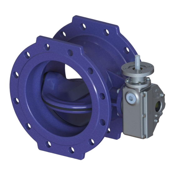
- Page 1 Operating Instructions Resilient Seated Butterfly Valves Type 4510 double flanged for water/ gas (PN 10/ 16/ 25) Item no. of the operating instructions: 764848 Issue 03, 2018 , 19 pages Specifications subject to change without notice Düker GmbH – www.dueker.de Issue 03 page 1...
-
Page 2: Table Of Contents
Intended use Safety precautions General safety instructions Safety instructions for the owner/operator Special risks Transport and storage Pressure test on the pipeline Installation into the pipeline General information Operational steps Functional description Drawing and parts list Drawing Part list Operation Troubleshooting Service and maintenance 10.1... -
Page 3: Intended Use
1 Intended use After the installation into a pipeline, butterfly valves are only intended for stopping or allowing media to pass within the range of the permitted operating conditions (temperature and pressure limit "PN" labeling on the valve, unless stated otherwise). These valves are preferably intended for liquid media, such as drinking water or gas. -
Page 4: Special Risks
Do not operate a valve whose permissible component operating pressure ("Ps") and maxi- mum permissible operating temperature ("Ts") are not sufficient for the operating condition. The area of application is marked on the valve. Within the permissible operating temperatures, there is a risk of injury when working on the piping components at temperatures below 10 °... -
Page 5: Transport And Storage
3 Transport and storage All valves must be carefully transported and stored. The valves are fully enameled or powder-coated. The coatings are shock-sensitive and must be protected against impact stress. The gaskets are sensitive to light: Unpackaged valves may only be exposed to bright daylight or ultraviolet light for a very short time. -
Page 6: Pressure Test On The Pipeline
4 Pressure test on the pipeline New installed pipelines should be carefully flushed first to wash out all foreign bodies. Valve open: The test pressure may not exceed the value 1.5 x PN (see valve markings). Valve closed: The test pressure may not exceed the value 1.1 x PN (see valve markings). 5 Installation into the pipeline 5.1 General information Only original spare parts from the manufacturer may be installed. -
Page 7: Operational Steps
5.2 Operational steps Transport the valve to the point of installation in its protective packaging. Remove all packaging materials from the valve. Check valve for transportation damage. Damaged valves must not be installed. Check coating for damages. The coating may be mended with a repair kit. ... -
Page 8: Drawing And Parts List
7 Drawing and parts list 7.1 Drawing Düker GmbH – www.dueker.de Issue 03 page 8... -
Page 9: Part List
7.2 Part list item description item description Body O-Ring Gear Box O-Ring Disk O-Ring Retaining Ring Hexagon Head Screw Shaft Washer Non-Drive Shaft Threaded Sleeve lower part Bearing Side A Threaded Sleeve upper part Bearing Side B Grub Screw Profile Seal O-Ring Blind pin Straight Pin... -
Page 10: Operation
8 Operation butterfly valve with hand wheel butterfly valve with electric actuator Düker GmbH – www.dueker.de Issue 03 page 10... - Page 11 Allocation of electrical actuators MT nom. AUMA Turns for AUMA Düker Gear Reduction Gear OPEN - Actuator Gear Type Input Type CLOSE Type (Nm) 10 - 16 10 – 16 SK I B / F10 10 – 16 SA 07.6 SK II B / F12 SK III B / F16 SA 10.2...
-
Page 12: Troubleshooting
9 Troubleshooting Leakage at a connection to the pipeline: Tighten the flange screws. If leakage continues: Repair necessary. Leakage at disc: Check if valve is 100% closed. If so, check if the valve has been closed with the required torque. ... -
Page 13: Service And Maintenance
10 Service and maintenance 10.1 Maintenance It is recommended to operate fittings that remain permanently in one position three to four times a year. 10.2 Replacing the profile sealing Mark the positon of the retaining ring (4) to the disc (3) (yellow line). Düker GmbH –... - Page 14 Loosen the countersunk screws (27) of the retaining ring when the valve is closed. Leave grub screws (23) untouched, because they reproduce the tensioned position of the profile sealing. Düker GmbH – www.dueker.de Issue 03 page 14...
- Page 15 Move the disc (3) to the open position and remove the countersunk screws (27). Remove the retaining ring (4) after removing the countersunk screws (27). Replace profile sealing (9), remove soiling in sealing area. Check the exact location of the profile sealing (9) in the retaining groove.
-
Page 16: Adjusting The Retaining Ring
In case of leakage, adjust retaining ring in closed position. To do this loosen grub screws (23) and tighten countersunk screws (27) with permissible torque. After this operation, turn the grub screws (23) clockwise to make contact with the surface of the butterfly disc (3). 10.3 Adjusting the retaining ring The retaining ring (4) can be adjusted in the CLOSED position of the butterfly valve. -
Page 17: Tightening Torque Gear Flange
10.4 Tightening torque gear flange Gearbox attachment A2-70 und A4-70 Dimension Permissible torque [Nm] Düker GmbH – www.dueker.de Issue 03 page 17... -
Page 18: Tightening Torque Blind Pin
10.5 Tightening torque blind pin Screws for fixing the blind pin A2-70 und A4-70 Dimension Permissible torque [Nm] 10.6 Tightening torque retaining ring Screws for fixing the retaining ring 100 – 300 350 – 600 700 – 1200 Dimension Permissible torque [Nm] 7 - 10 10 -12 12 - 15... - Page 19 The distribution and reproduction of these Operating Instructions, utilization and communication of their con- tents to others is authorized exclusively for the purpose of ensuring the correct installation and operation of the Düker product treated in the document. For all other purposes, distribution, reproduction and utilization of the contents, also in excerpts, is prohibited.
Need help?
Do you have a question about the 4510 Series and is the answer not in the manual?
Questions and answers