Advertisement
Quick Links
Advertisement

Summary of Contents for EPK Distortion Plus
- Page 1 Distortion Plus Building Manual...
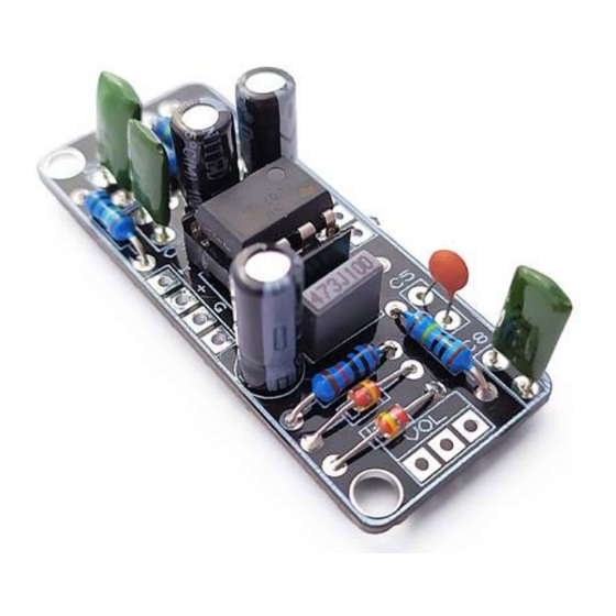
- Page 2 Effect Pedal Kits: The Distortion Plus kit is a vintage distortion based in the original MXR Distortion+ that has been around for more than 40 years! It uses an operational amplifier along with two germanium diodes to produce a crunchy clipping perfect for metal. Some guitarist that use or have used it are Randy Rhoads with Ozzy Osbourne, Dave Murray of Iron Maiden and Thom Yorke of Radiohead.
- Page 3 BOM (1/2) Resistors (8) Capacitors (8) R1, R2, R3, R5, R7 C1, C7 1u (electrolytic) R4, R8 10u (electrolytic) 4.7k C3, C8 10p (ceramic)
- Page 4 BOM (2/2) Diodes, Transistors and ICs Generic Parts and Potentiometers TL071 Battery clip D1, D2 1N4148 DC Jack RLED 1k LED resistor LED Bezel 3PDT IN, OUT 6.35mm Jacks 500kB Gain 50kA...
-
Page 5: Component Placement
Component Placement... -
Page 6: Board Layouts
Board Layouts 3PDT PCB Effect PCB... - Page 7 Building Tips 1- Pay attention to the orientation of the 3PDT! In the following picture you can see how the 3PDT pins should be positioned (inserting the pins in the holes can be a bit tight to avoid movement while soldering): 2- For a proper soldering you just have to apply the right amount of solder wire.
- Page 8 Building Tips 5- Pay attention to the parts that have a polarity and make sure they are connected as in the component placement picture: - ICs (they have a small dot or indication that must fit the indication in the board - Electrolytic capacitors (longer pin is connected to the “+”...
- Page 9 Building Tips 6- With the kit we include plastic PCB supports with an adhesive bottom. You can use them to anchor the PCB to your enclosure for a better stability. Just insert the PCB support tip into the 3.5mm holes and remove the adhesive protective film.
- Page 10 Schematic...
Need help?
Do you have a question about the Distortion Plus and is the answer not in the manual?
Questions and answers