Advertisement
Quick Links
Advertisement

Summary of Contents for EPK FET
- Page 1 FET Preamp Kit Building Manual...
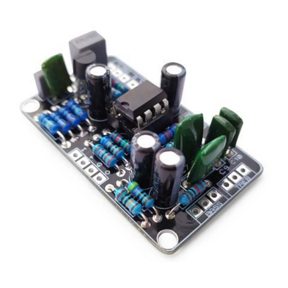
- Page 2 The FET Preamp is a very clean boost perfect to get a bit more of volume or help your tube amp to break up in a natural and warm way.
- Page 3 BOM (1/2) Resistors (16) Capacitors (11) R1, R3 R2, R7, R13 C2, C5, C6, C11 10u (electrolytic) 6.8k 470n R6, R9 C7, C8 R8, R10 470k C9, C10 4.7n R11, R14 8.2k 100k...
- Page 4 BOM (2/2) Diodes, Transistors and ICs Generic Parts and Potentiometers TL072 Battery clip J113 DC Jack RLED 1k LED resistor LED Bezel 3PDT IN, OUT 6.35mm Jacks 50kB (Linear) Potentiometer BASS, TREB 1MA (Logarithmic) Potentiometer SPDT...
-
Page 5: Component Placement
Component Placement... -
Page 6: Board Layouts
Board Layouts 3PDT PCB Effect PCB... - Page 7 Building Tips 1- Pay attention to the orientation of the 3PDT! In the following picture you can see how the 3PDT pins should be positioned (inserting the pins in the holes can be a bit tight to avoid movement while soldering): 2- For a proper soldering you just have to apply the right amount of solder wire.
- Page 8 Building Tips 5- Pay attention to the parts that have a polarity and make sure they are connected as in the component placement picture: - ICs (they have a small dot or indication that must fit the indication in the board - Electrolytic capacitors (longer pin is connected to the “+”...
- Page 9 Building Tips 6- With the kit we include plastic PCB supports with an adhesive bottom. You can use them to anchor the PCB to your enclosure for a better stability. Just insert the PCB support tip into the 3.5mm holes and remove the adhesive protective film.
- Page 10 Schematic...
Need help?
Do you have a question about the FET and is the answer not in the manual?
Questions and answers