Advertisement
Table of Contents
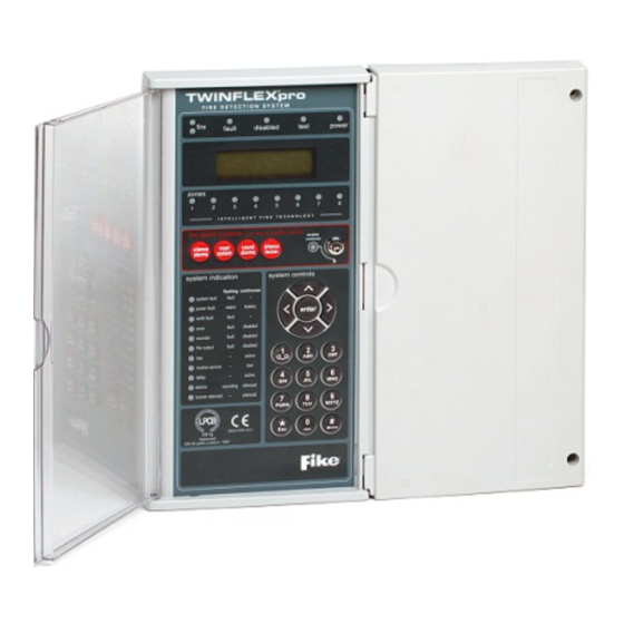
INSTALLATION AND MAINTENANCE INSTRUCTIONS
505-0006 TWINFLEX
General Description
®
The TWINFLEX
pro Expansion Card allows a 4 zone TWINFLEX
The card is only compatible with the 4-zone TWINFLEX
®
TWINFLEX
pro panel or with any earlier TWINFLEX
Installation
The panel must be completely powered down before this card is fitted.
1. Remove the right hand cover moulding from the unit by unscrewing the two fixing screws.
2. Next disconnect the battery by removing one of the push on battery leads at the battery. Always disconnect
the battery first before removing the mains power to the panel.
NOTE: Do not disconnect the battery by removing the wires from the terminals on the CIE circuit
board. Doing this may allow the batteries to short circuit.
3. Remove mains power from the panel by removing the fuse in the fused spur that supplies the panel or
switching off the circuit breaker. At this stage there should be no LEDs lit on the panel and the display
should be blank.
4. Disconnect all cabling from the CIE terminals. Make sure these cables are suitably labelled to facilitate
correct re-connection after fitting the Expansion Card.
5. Unscrew the two fixing screws that secure the left hand CIE assembly, then slide the assembly to the left
and flip the assembly over clockwise.
®
pro Expansion Card
®
pro panel. It is not compatible with the 2-zone
®
or TWINFLEX
®
pro panel to be converted to an 8 zone panel.
®
Checkpoint Plus panels.
26-1135 Issue 1
Advertisement
Table of Contents

Summary of Contents for Fike Twinflex pro 505-0006
- Page 1 INSTALLATION AND MAINTENANCE INSTRUCTIONS ® 505-0006 TWINFLEX pro Expansion Card General Description ® ® The TWINFLEX pro Expansion Card allows a 4 zone TWINFLEX pro panel to be converted to an 8 zone panel. ® The card is only compatible with the 4-zone TWINFLEX pro panel.
- Page 2 6. Secure the expansion card PCB to the unit’s base using the 4 off M3 x 6 screws supplied. Please note the orientation of the expansion card PCB. 7. Plug one end of the ribbon cable assembly into the expansion card PCB (this will only fit one way). 8.
- Page 3 10. Re-connect all existing cables to the appropriate terminals. 11. If the new additional zones are to be used straight away, connect the additional field wiring zone cables to ® the relevant terminals on the TWINFLEX pro panel CIE (they do not connect directly to the Expansion ®...
- Page 4 Fike’s policy is one of continual improvement and the right to change a specification at any time without notice is reserved. Whilst every care has been taken to ensure that the contents of this document are correct at time of publication, Fike shall be under no liability whatsoever in respect of such contents.
Need help?
Do you have a question about the Twinflex pro 505-0006 and is the answer not in the manual?
Questions and answers