Dometic B3300 Installation & Operating Instructions Manual
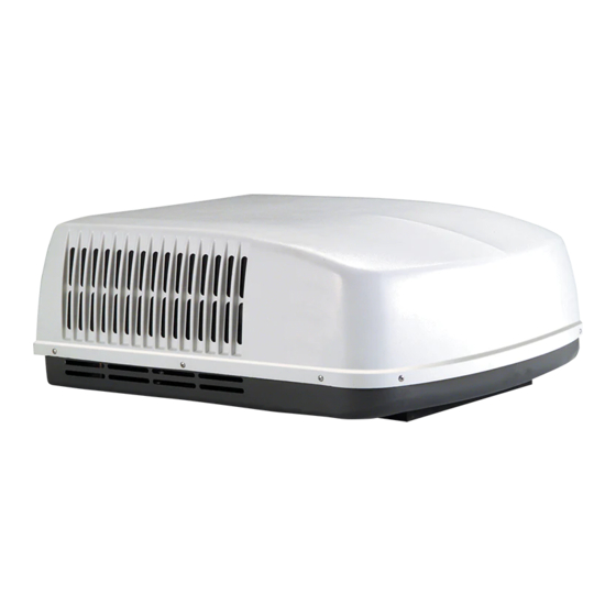
Durasea roof top air conditioner
Hide thumbs
Also See for B3300:
- Installation & operating instructions manual (12 pages) ,
- Installation & operating instructions manual (15 pages)
Table of Contents
Advertisement
REVISION B
Form No. 3315827.000 08/16
©2016 Dometic Corporation
LaGrange, IN 46761
DuraSea Roof Top Air Conditioner
Description
Model
Air Conditioner
B3300
RECORD THIS INFORMATION FOR FUTURE
REFERENCE:
Model Number
Serial Number
ADB Model Number
ADB Serial Number
Date Purchased
Roof Top Unit
Type
Use With Air Distribution Box (not included)
Model
3341P
3314865.000
83341A
Read these instructions carefully. These
instructions MUST stay with this product.
Control
Integral Mechanical
SERVICE CENTER &
DEALER LOCATIONS
Please Visit:
www.eDometic.com
Advertisement
Table of Contents

Related Manuals for Dometic B3300


Summary of Contents for Dometic B3300
- Page 1 Control Air Conditioner B3300 3341P 3314865.000 Integral Mechanical 83341A Read these instructions carefully. These instructions MUST stay with this product. SERVICE CENTER & REVISION B DEALER LOCATIONS Form No. 3315827.000 08/16 Please Visit: ©2016 Dometic Corporation www.eDometic.com LaGrange, IN 46761...
-
Page 2: Table Of Contents
This unit can be installed by one person with brief help from additional personnel. Use these instructions to ensure a properly installed, and properly functioning product. Dometic Corporation reserves the right to modify appearances and specifications without notice. TABLE OF CONTENTS INTRODUCTION ..................................2... -
Page 3: Document Symbols
● This product MUST be [installed / serviced] by a qualified service technician. ● Do NOT modify this product in any way. Modifica- tion can be extremely hazardous. ● Do NOT add any devices or accessories to this product except those specifically authorized in writing by Dometic Corporation. -
Page 4: Specifications
2 Unit - 5.0 kW Rating Plate 3313169.000 Height 333 mm Width 759 mm Depth 886 mm Weight 46.7 kg * Dometic Marine gives GENERAL guidelines for genera- tor requirements. To reduce start-up power draw by up to 65%, consider installing a Dometic SmartStart. -
Page 5: Installation Instructions
INSTALLATION INSTRUCTIONS Choosing Proper Location For Unit FIG. 2 This unit is specifically designed for installation on the roof 537 mm 587 mm of a boat. Mount only with front of unit facing the bow (the vented end should face aft). See “FIG. 4” on page (6). When determining your cooling requirements, the following 67 mm should be considered:... -
Page 6: Wiring Requirements
INSTALLATION INSTRUCTIONS FIG. 3 FIG. 4 Lift And Place Rear Front Good-Rafters Good Location Do Not Cut Roof Supported By Between Roof Structure Or Front Towards Bow Rafters Cross Beams Rafters Frame Opening So It 19 mm Min. Won't Collapse When Bolting Down Unit Do Not Slide 4. - Page 7 INSTALLATION INSTRUCTIONS c. Carefully install the duct divider in the roof FIG. 6 opening 143 mm from back of roof opening. See (FIG. 9). Ceiling Duct Divider Foil back faces rear of unit. Template Base Pan FIG. 9 Duct Divider Front Control 143 mm From Back...
-
Page 8: Wiring System
INSTALLATION INSTRUCTIONS f. Hold the ceiling template up to the roof open- FIG. 13 ing and line up the channel in the ceiling template with the previously installed duct divider. See (FIG. 11). FIG. 11 Duct Divider Channel h. Tighten mounting bolts to correct torque specifications. -
Page 9: Installing Adb
INSTALLATION INSTRUCTIONS FIG. 14 FIG. 15 Ceiling Template Alignment Holes Black Wire Wire Green Wire Junction Box Junction Cover Screw Box Cover d. If a plug in connection; Use the electric sup- ADB Alignment Holes ply wire to power an electrical outlet (in- stalled according to applicable laws) at the end of the roof opening farthermost from the junction box. - Page 10 INSTALLATION INSTRUCTIONS 2. Install two (2) (supplied) sheet metal screws in- FIG. 19 side return air opening to secure ADB to ceiling template. See (FIG. 17). 3. Install eight (8) (supplied) wood screws inside Slot In ADB the front, rear, and side doors to secure ADB to ceiling.
-
Page 11: Operating Instructions
OPERATING INSTRUCTIONS Controls Heating Operation (Red Graphic) With Electric Heater Option Installed 1. The selector switch has ten positions including “OFF”. It controls the fan speeds, cooling modes, T he heating mode of operation will NOT re- and heating modes of operation. See (FIG. 21). place a furnace for heating your boat in cold weather. -
Page 12: Maintenance
MAINTENANCE Air Filter ADB Housing 1. Periodically (a minimum of every 2 weeks of op- 1. Clean ADB housing and control panel with a soft eration) remove the return air filter located be- cloth dampened with a mild detergent. Never hind the return air vent grille and wash it with use furniture polish or scouring powders. -
Page 13: Service - Unit Does Not Operate
● Go to WWW.dometic.com/marinedealers or ● Check your fuse or circuit breaker to see if it is ● Call Dometic Marine at 1-800-542-2477 8:00 open. Insure fuse is not burnt, or circuit breaker AM to 5:00 PM Eastern Time, or 1-888-440- is “ON”... -
Page 14: Owner's Limited Warranty
Dometic reserves the right to improve its products, through changes in design or material without being obligated to incorporate such changes in products of prior manufacture. Dometic can make changes at any time in design, materials, or part of units of any one, model year, without obligation or liability to owners of units of the same year’s model of prior manufacture. -
Page 15: Coverage Period
Dometic warranty as described in Section A. For proof of date put in service, Dometic will require a copy of the bill of sale of the Dometic equipment from the installer or new boat dealer to the original owner. -
Page 16: Table Of Warranty Periods
DOMETIC DURASEA ROOFTOP AIR CONDITIONING Important Notes: 1. Warranty periods begin from the date of possession of the boat by the first owner if OEM installed or date of installation if dealer installed, but not to exceed three (3) years from date of production. The warranty is transferable and will carry the remainder of the original owner's warranty based on the original date of pur- chase or date of installation.
Need help?
Do you have a question about the B3300 and is the answer not in the manual?
Questions and answers