
Related Manuals for Allworx Powerflex G810

Summary of Contents for Allworx Powerflex G810
- Page 1 ® Allworx POWERFLEX G810 Managed GbE PoE Switch Quick Installation and Initial Configuration Guide Version A: Updated August 16, 2017...
- Page 3 POWERFLEX G810 Managed GbE PoE Switch Quick Installation and Initial Configuration Guide...
- Page 4 A N A G E M E N T U I D E...
-
Page 5: Table Of Contents
POWERFLEX G810 Managed GbE PoE Switch Quick Installation and Initial Configuration Guide Contents Chapter 1 Introduction ..........1 Overview ..................1 Front View of the Switch ............1 Rear View of the Switch ............. 2 LED Descriptions ................2 Mode/Reset Button ..............4 Chapter 2 Installing the Switch ...... -
Page 6: Chapter 1 Introduction
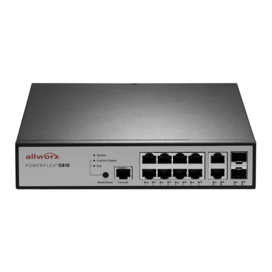
POWERFLEX G810 Managed GbE PoE Switch Quick Installation and Initial Configuration Guide Chapter 1 Introduction Overview This user guide describes how to install, configure, and troubleshoot the POWERFLEX G810 Managed GbE PoE Switch. By reading this user guide, users can perform the following tasks: To check the switch status by reading the LED behavior •... -
Page 7: Rear View Of The Switch
POWERFLEX G810 Managed GbE PoE Switch Quick Installation and Initial Configuration Guide Rear View of the Switch Figure 2: Rear panel of the switch LED Descriptions The LEDs on the front panel provide users with switch status checking and monitoring. There are three types of LEDs as follows: System LED •... - Page 8 POWERFLEX G810 Managed GbE PoE Switch Quick Installation and Initial Configuration Guide Table 2: Mode LEDs Color State Description The Port Status LEDs are displaying link Link/Act/Speed Green status, network activity and speed of each port. The RJ45 Port Status LEDs are displaying Green PoE powering status of each port.
-
Page 9: Mode/Reset Button
POWERFLEX G810 Managed GbE PoE Switch Quick Installation and Initial Configuration Guide When PoE Mode LED Lit LED Color State Description The port is enabled and supplying power to connected Green device. An abnormal state, such as overload status, has been... - Page 10 POWERFLEX G810 Managed GbE PoE Switch Quick Installation and Initial Configuration Guide Table 4: Mode/Reset Button Descriptions Task to be Time Period of SYS LED Port Status LED Performed Pressing Button Behavior Behavior LED status will be Change LED Mode...
-
Page 11: Chapter 2 Installing The Switch
POWERFLEX G810 Managed GbE PoE Switch Quick Installation and Initial Configuration Guide Chapter 2 Installing the Switch Package Contents The Switch • AC Power cord • Console cable • Four adhesive rubber feet • Note The switch is an indoor device. If it is to be used with outdoor devices... -
Page 12: Mounting The Switch On Desk Or Shelf
POWERFLEX G810 Managed GbE PoE Switch Quick Installation and Initial Configuration Guide Step 2: make sure that the switch is attached securely to wall. Figure 4: Attaching switch to the wall Mounting the Switch on Desk or Shelf Step 1: Verify that the workbench is sturdy and reliably grounded. -
Page 13: Connecting The Ac Power Cord
POWERFLEX G810 Managed GbE PoE Switch Quick Installation and Initial Configuration Guide Connecting the AC Power Cord Step 1: Connect the AC power cord to the AC power receptacle of switch. Step 2: Connect the other end of the AC power cord to the AC power outlet. - Page 14 POWERFLEX G810 Managed GbE PoE Switch Quick Installation and Initial Configuration Guide Figure 7: Installing a SFP Module into a SFP Port Note The SFP ports should use UL Listed Optional Transceiver product, Rated 3.3Vdc, Laser Class 1. Page 9 Toll Free 1-866-ALLWORX •...
-
Page 15: Chapter 3 Initial Configuration Of Switch
POWERFLEX G810 Managed GbE PoE Switch Quick Installation and Initial Configuration Guide Chapter 3 Initial Configuration of Switch Initial Switch Configuration Using Web Browsers After powering up the switch for the first time, you can perform the initial switch configuration using a web browser. For managing other switch features, please refer to the Web interface user guide for details. - Page 16 POWERFLEX G810 Managed GbE PoE Switch Quick Installation and Initial Configuration Guide Step 1: Type “network and sharing“ into the Search box in the Start Menu Step 2: Select Network and Sharing Center Step 3: Click on Change adapter settings on the left of PC screen...
- Page 17 POWERFLEX G810 Managed GbE PoE Switch Quick Installation and Initial Configuration Guide 5. Run your Web browser on the PC, enter the factory default IP address, so as to access the switch’s Web interface. If your PC is configured correctly, you will see the login page of the switch as shown by Figure 9 below.
-
Page 18: Chapter 4 Troubleshooting
POWERFLEX G810 Managed GbE PoE Switch Quick Installation and Initial Configuration Guide Chapter 4 Troubleshooting The following table provides information for users to easily troubleshoot problems by taking actions based on the suggested solutions within. Table 5: Troubleshooting Table Possible... - Page 20 Toll Free 1-866-ALLWORX • 585-421-3850 www.allworx.com Version: A Revised August 16, 2017...
Need help?
Do you have a question about the Powerflex G810 and is the answer not in the manual?
Questions and answers