Table of Contents
Advertisement
Quick Links
Advertisement
Table of Contents
Troubleshooting

Summary of Contents for AmeriWater MROX Series
- Page 1 MROX OPERATION & MAINTENANCE MANUAL FOR MODELS MRO2X, MRO3X, MRO4X AND MRO5X FOR CENTRAL SYSTEM APPLICATIONS Manufactured With Pride In The USA www.ameriwater.com • 800-535-5585 AmeriWater • 3345 Stop 8 Road • Dayton, OH 45414 PN 98-0058 Rev. R...
- Page 3 CAUTIONARY SYMBOLS Caution, risk of electrical shock! Attention, risque de choc électrique! Open by qualified service personnel only! Ouverture par le personnel qualifié seulement! Refer to this Operation and Maintenance Manual for instructions and safety considerations. Référez-vous au manuel des Opérations et Entretien pour instructions et mesures de sécurité.
-
Page 4: Table Of Contents
TABLE OF CONTENTS SECTION 1, GENERAL INFORMATION ..........................1 INTRODUCTION ................................1 RESTRICTION ON USE ..............................1 SECTION 2, TECHNICAL INFORMATION ..........................2 SPECIFICATIONS ................................2 POWER RATINGS ................................ 3 MRO OUTPUT WATER QUALITY ..........................3 TEMPERATURE CORRECTED MRO PRODUCTION RATES ..................... 4 ENVIRONMENTAL/TRANSPORT CONDITIONS EXPECTED ................... -
Page 5: Section 1, General Information
Discard all product water for at least two hours of operation before placing the RO in service. CAUTION: No person should attempt to operate or service the AmeriWater MRO without prior authorization, instruction, and training from AmeriWater and/or your medical facility director. -
Page 6: Section 2, Technical Information
SECTION 2, TECHNICAL INFORMATION SPECIFICATIONS Ideal, minimum, and maximum Min = 41° F (5° C) Max = 90° F (33° C) incoming water temperature Ideal Temperature = 77° F (25° C) Prefilter gauge pressure (when the MRO is running) 20 PSI Minimum 90 PSI (Pounds per Square Inch) Maximum... -
Page 7: Power Ratings
The physician in charge of dialysis has the ultimate responsibility for selecting the maximum allowable levels of chemical contaminants in the water, and, also, is responsible for monitoring the water. The AmeriWater MRO System is designed to produce water that meets or exceeds ANSI/AAMI RD62 requirements. -
Page 8: Temperature Corrected Mro Production Rates
TEMPERATURE CORRECTED MRO PRODUCTION RATES MRO membrane performance is affected by water temperature. The Product Water Flow Rate and Output decreases as the temperature of the Incoming Tap Water decreases. ENVIRONMENTAL/TRANSPORT CONDITIONS EXPECTED ENVIRONMENTAL CONDITIONS ANTICIPATED This device is intended to be used under the following conditions: Indoor use;... -
Page 9: Section 3, Components And Schematics
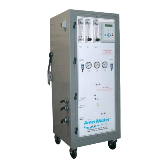
SECTION 3, COMPONENTS AND SCHEMATICS EXTERNAL FRONT VIEW MRO2X – 5X Manual - 5 - 98-0058 Rev. R... - Page 10 IDENTIFICATION OF COMPONENTS (EXTERNAL FRONT VIEW) PRODUCT GPM: Rotameter that measures the flow of the Product Water For Dialysis in gallons per minute (GPM). SIDE ENTRY HOOD: External wire installation for float level switches, pretreat lockout and RO alarm relay connectors; (See Section 7). REJECT GPM WITH VALVE: Rotameter with valve to control the flow of the Reject water to drain, in gallons per minute (GPM).
-
Page 11: Internal Rear View
INTERNAL REAR VIEW MRO2X – 5X Manual - 7 - 98-0058 Rev. R... - Page 12 (CIP) switch is placed to the ON position, all RO+ fail-safe modes are disabled for low- pressure membrane cleaning with the optional AmeriWater Clean In Place system (P/N 00CIP2). The controller will display a warning that the CIP mode is active.
-
Page 13: Electrical Diagram, Mro2X, Mro3X, Mro4X & Mro5X
ELECTRICAL DIAGRAM, MRO2X, MRO3X, MRO4X & MRO5X MRO2X – 5X Manual - 9 - 98-0058 Rev. R... -
Page 14: 3.4 Fluid Diagram, Mro2X, Mro3X & Mro4X
3.4 FLUID DIAGRAM, MRO2X, MRO3X & MRO4X MRO2X – 5X Manual - 10 - 98-0058 Rev. R... -
Page 15: Fluid Diagram Mro5X
FLUID DIAGRAM MRO5X MRO2X – 5X Manual - 11 - 98-0058 Rev. R... -
Page 16: Section 4, Mro Startup & Operation
SECTION 4, MRO STARTUP & OPERATION CAUTION NOTE: This entire Operations Manual should be read before operating or servicing the MRO system. The Operations Manual should then be kept near the system and used as a reference and troubleshooting guide. WARNING: This Reverse Osmosis System (RO) contains a preservative solution to prevent microbiological growth and freezing. - Page 17 verify that it is within the specified range (pH Water/Bicarbonate/Dialysate Test Strips P/N 97PH20901). CAUTION: Mixing chlorine and hydrogen peroxide/peroxyacetic acid causes a toxic chemical reaction. Never allow them to mix! Do not use chlorine to disinfect the system! 8. Use only the exact amount of hydrogen peroxide/peroxyacetic acid disinfectant solution (PAA) and in proper dilution during disinfection of the system.
-
Page 18: Safety Features
4. An audible alarm sounds whenever water quality drops to an unacceptable level. WARNING: The AmeriWater model MRO 2X through 5X is considered a non-portable device. It can be connected to a Direct Feed Loop system or a Storage Tank system. -
Page 19: Initial Startup
INITIAL STARTUP WARNING: This Reverse Osmosis System (RO) contains a preservative solution to prevent microbiological growth and freezing. Discard all product water for at least two hours of operation before placing the RO in service. 1. Lock the two front casters so that the RO+ will remain stationary during startup. 2. - Page 20 AAMI standards, distribution of the water may degrade its quality to the point where it no longer meets the requirements of this standard. AmeriWater offers information about ultra pure water piping to prevent the degradation of product water in a water loop or central system.
-
Page 21: System Shutdown
SYSTEM SHUTDOWN Ordinarily, an MRO2-5X is connected to a water use system that is used continually or very frequently. Therefore, frequent shutting down is not necessary. Most usually, the MRO is connected to a Direct Feed Loop or Storage Tank of a Central System. If so, the MRO should be cycled using the “Membrane Flush”... -
Page 22: Section 5, Disinfecting The System
As a general guideline, AmeriWater recommends that the system should be disinfected at least monthly. In addition, AmeriWater recommends that the system be disinfected if it has not been: used for 24 hours; flushed at least every 8 hours; or “packed” in BioTrol for storage up to two weeks. - Page 23 To disinfect the MRO AND “small” direct-feed water loop, allow the PRODUCT WATER hose to remain connected to the “small” loop during the disinfection procedure, but be sure all dialysis machines are disconnected during the disinfection procedure. Unscrew the cap assembly of the PAA container (plastic 2 ½ gallon container). Put on rubber gloves, apron, and goggles.
- Page 24 14b. If disinfecting the MRO while connected to a small direct-feed loop: Draw a complete PAA container into the MRO (with the REJECT flow amount adjusted as needed described in step 12). Release the ENTER key, then refill the PAA container, reconnect the PAA container to the MRO, press &...
- Page 25 PRODUCT WATER hose connection. After each container of PAA solution is drawn into the MRO, then the MRO must be stopped without delay, and each water outlet must be tested for PAA at the minimum amount. Continuing to run the MRO after all the PAA solution is drawn out of the PAA container will only result with diluting the strength of the PAA, which reduces the disinfecting capability.
- Page 26 (no color change) to ensure that there are NO traces of PAA disinfecting solution remaining in the entire water system. AmeriWater recommends using Renal Check PX Test Strips (P/N 97PX20501) Record the Stop time on the Startup Log to have a record of how long it takes for the disinfecting solution to completely rinse out.
-
Page 27: Disinfecting An Mro And "Large" Loop System
This is good for cleaning, but great care must be exercised for disinfection. To clean an MRO an AmeriWater CIP2 cleaning system is required to be connected to the MRO. -
Page 28: A Word About Hydrogen Peroxide/Peroxyacetic Acid
A WORD ABOUT HYDROGEN PEROXIDE/PEROXYACETIC ACID Do not use hydrogen peroxide/peroxyacetic acid concentrate (PAA) after the expiration date. Using outdated PAA may cause incomplete disinfection. PAA loses effectiveness if not kept out of direct sunlight and/or the cap is not tightly sealed. Using ineffective disinfecting solution will cause incomplete disinfection. -
Page 29: Membrane Flush Feature (Auto Flush)
The Flush Time and Flush Interval settings are recommended settings, but may be adjusted to fit your specific needs. Contact your AmeriWater representative for guidance. MRO2X – 5X Manual - 25 - 98-0058 Rev. -
Page 30: Section 6, Mro Controller
SECTION 6, MRO CONTROLLER FRONT PANEL CONTROLS AND INDICATORS FIGURE 6.1 DISPLAY DISPLAY - Shows status of system. ALARM LAMP - Flashes when fault causes an RO system shut down. On steady when a Setpoint is exceeded that does not cause an RO system shut down. -
Page 31: Controller Operation
CONTROLLER OPERATION GENERAL OPERATION The unit has 2 modes of operation, a standby mode and an operating mode that are controlled by the POWER key. In the standby mode, the unit is effectively off. All outputs are turned off and the display shows STANDBY. In the operating mode, the unit operates automatically. All inputs are monitored and the outputs are controlled accordingly. - Page 32 CONDUCTIVITY The Conductivity is shown on the top line after the unit operating status. When the unit is in STANDBY, because of a shut down condition, the reading is replaced with ‘----’. If the reading is over range, the reading is shown as ‘^^^^’ when in the OPERATE mode. OPERATING HOURS The current operating hours are shown on the bottom line.
- Page 33 TANK FULL OVERRIDE A timed tank full override can be initiated when the MRO unit is shut down due to a tank full condition. Pressing the Alarm Silence/Reset key for 3 seconds during a tank full condition will enable the tank full override. The RO will start and TF OVERRIDE 9 will show on the display. The number is the minutes remaining in the override timer.
-
Page 34: Controller Adjustments
It may be necessary to periodically calibrate the Conductivity. If the controller should require calibration, follow the instructions below. Please contact AmeriWater at 800/535-5585 or 937/461-8833 if you have any questions regarding the procedure. - Page 35 FIGURE 6.2 MRO2X – 5X Manual - 31 - 98-0058 Rev. R...
- Page 36 FIGURE 6.3 MRO2X – 5X Manual - 32 - 98-0058 Rev. R...
-
Page 37: Standard Setpoints
STANDARD SETPOINTS FACTORY SETPOINT DESCRIPTION RANGE SETTING When this value is met or exceeded, the alarm Based on 0-999 TDS/Cond Limit lamp will light and high TDS/Cond will show on water µS or PPM* the display. To disable, set to 0. analysis. - Page 38 FACTORY SETPOINT DESCRIPTION RANGE SETTING The interval between flush cycles. Only valid 0-99 Flush Interval with operation hour, elapsed time or off flush minutes types. Selects if the inlet and RO pump relays Flush Mode operate during flush. If the current operating hours exceed this 0-65000 Maximum Hours limit, the operating hours warning will occur.
-
Page 39: To Display Or Change Setpoints
TO DISPLAY OR CHANGE SETPOINTS NOTE: Please contact your AmeriWater representative prior to changing set points. 1. Refer to Figure 6.1 for the location of the keys used to display or change the Setpoints and Figure 6.2 for the location of the write protect jumper, J3. For the unit to be able to accept a change in a Setpoint, the shorting jumper must be in the WRITE PROTECT OFF position (center and left pins). -
Page 40: Section 7, External Wire Installation
SECTION 7, EXTERNAL WIRE INSTALLATION FLOAT LEVEL SWITCHES, PRETREAT LOCKOUT & RO ALARM RELAY CONNECTORS Remove the side entry hood by disengaging the lock and pulling down. Loosen 4 retaining screws from outer shroud and remove inner terminals. Loosen the nut and run the float switch wires through the outer housing. Connect the High Tank float wires to contacts 1 &... -
Page 41: Section 8, Maintenance
WARNING: Maintenance shall be performed by qualified personnel only. MAINTAINING THE SYSTEM 1. AmeriWater has provided a Startup Log for the MRO system. This must be filled out completely each time the system is used. The recorded information may be useful in troubleshooting problems encountered with the MRO. -
Page 42: Pt401 Anti-Scalant
PT401 ANTI-SCALANT Smaller AmeriWater MRO products have the PT401 antiscalant system equipped as an option. The larger units, MRO2-5X4 ordinarily have a complete water pre-treatment system (backwashing particulate filter, backwashing carbon filter, and water softener) installed ahead of the MRO. This eliminates the need for the PT401 anti-scalant system within the MRO, and is not a point of discussion in this manual. - Page 43 8. Turn on the RO+. The rinse out cycle is now complete, and the RO+ is ready for use. WARNING: If the product water conductivity does not come out of alarm, do not use the system! Continue rinsing, or call AmeriWater for guidance. MRO2X – 5X Manual - 39 - 98-0058 Rev.
-
Page 44: Section 9, Troubleshooting And Repair
MRO system. To assist you in quickly restoring your system into service, AmeriWater will send your replacement part out immediately and check your bad part when it comes in to verify if it is covered under your equipment warranty. - Page 45 PROBLEM POSSIBLE CAUSE CORRECTIVE ACTION Disinfect cycle will not DISINFECT MODE has not Access DISINFECT MODE operate when holding the been accessed correctly. (see Section 5.1). ENTER key Circuit board relay not Replace the controller circuit operating in DISINFECT board (see Section 9.2). MODE.
- Page 46 PROBLEM POSSIBLE CAUSE CORRECTIVE ACTION Low product flow rate Low pressure feeding Verify that the incoming tap membrane water supply is fully open. The pressure on the prefilter gauges should be > 20 PSI when the MRO is operating. Low pump PSI Pump should be operating at 175 –...
-
Page 47: Controller Troubleshooting
When disconnecting or connecting any board or accessory, be sure power is unplugged. Before contacting AmeriWater for technical help, verify the programming of all Setpoints, check the display and check the status of all lights and indicators. The more information available when you contact us, the easier it will be to determine the source of the problem. - Page 48 PROBLEM INVESTIGATION CORRECTIVE ACTION RO Pump Will Not Operate Is the system in standby? (Cont.) If no, are any shut down conditions active? If no, is the RO LED, DS6 lit? If no, replace the board. If yes, with a voltmeter, verify If no, replace the board.
-
Page 49: Pump Repair
PUMP REPAIR The following procedures are instructions for removing the pump from the unit. The MRO5X Series has a 3HP pump with a .75 throttle valve. The repair and removal on the MRO5X is slightly different. The differences are noted in the instructions below where applicable. Before replacing the pump, be sure the pump’s thermal overload has not tripped. -
Page 50: Solenoid Test Procedure
5. Insert the pump assembly and reconnect the pump to the frame using the unistrut clamps. 6. Connect the membrane feed tubing and pump pressure gauge tubing to the pump housing outlet port (at the top), and tighten the ferrule nut. On the MRO5X, connect the pump discharge hose to the inlet connection on the 1 membrane housing by tightening the fitting , install the throttle valve with hose, tee, nipple... -
Page 51: Solenoid Valve Replacement
14. To verify that the solenoid valve is installed correctly, follow the Solenoid Test Procedures in Section 9.5. SECTION 10, WARRANTY This product is covered under the standard AmeriWater warranty policy. For specific terms and conditions, please contact your AmeriWater Sales Representative. MRO2X – 5X Manual... -
Page 52: Spare Parts Listing
SECTION 11 SPARE PARTS LISTING MRO2X – 5X Manual - 48 - 98-0058 Rev. R... - Page 53 MRO2X – 5X Manual - 49 - 98-0058 Rev. R...
-
Page 54: Routine Replacement Items (Non-Durable Components)
For Measuring Low Level Chlorine/Chloramine LAL Endotoxin Testing, Exact results in just a few days AAMI AAMI Chemical Analysis, Results within one week *Call AmeriWater or your AmeriWater distributor for pricing. MRO2X – 5X Manual - 50 - 98-0058 Rev. R... - Page 55 EXPLANATION OF THE 0013-0002 O-RING REPLACEMENT KIT FOR THE 24-0007 MEMBRANE HOUSING The 24-0007 membrane housing is purchased from (2) different vendors, Pureteck & Axeon. To identify the correct housing being used with your product, reference the pictures below. The 0013-0002 o-ring kit contains a quantity of (2) of the 24-0029 o-rings and a quantity of (2) of the 24-0028 u-packing seals that are used on the Pureteck membrane housing for the (2) end caps.
Need help?
Do you have a question about the MROX Series and is the answer not in the manual?
Questions and answers