
Related Manuals for metrotek Bercut-ET

Summary of Contents for metrotek Bercut-ET
- Page 1 Ethernet/Gigabit Ethernet Tester Analyzer Bercut-ET Operations manual Version 1.1.0, 2009 Metrotek...
- Page 2 No part of this document may be reproduced in any form or by any means without the express written permission of Metrotek. Metrotek retains the right to make changes to the hardware, software of Bercut-ET and to this document at any time, without notice.
-
Page 3: Table Of Contents
Back-to-back. Test results ....35 5.7 Asymmetric test ......36 Bercut-ET. Operations manual... - Page 4 5.22.5 Battery ......92 5.22.6 Managing options ..... 92 Bercut-ET. Operations manual...
- Page 5 6.4 Screen shot ......99 A Ethernet frame structure B Remote control commands C Specifications and Technical characteristics D Troubleshooting Bibliography Bercut-ET. Operations manual...
- Page 6 Bercut-ET. Operations manual...
-
Page 7: General Description
1. General description Ethernet/Gigabit Ethernet tester-analyzer Bercut-ET (referred to as de- vice, analyzer) is intended for performing analysis and diagnostic tests ac- cording to the RFC 2544 [5] methodology, checking the state of a cable, and checking link connectivity. In addition, the analyzer supports operations in the loopback mode, and statistics getting for received and transmitted traffic. - Page 8 Bercut-ET. Operations manual...
-
Page 9: Supply Kit
2. Supply kit Table 2.1. Supply kit Item Quantity Ethernet/Gigabit Ethernet tester-analyzer Bercut-ET de- vice Ethernet/Gigabit Ethernet tester-analyzer Bercut-ET. Op- erational manual Power supply unit (12 V, 1,5 A) Cable (220 V, 3-polar) USB cable Ethernet cable Bercut-ET. Operations manual... - Page 10 Bercut-ET. Operations manual...
-
Page 11: Setting-Up Procedures
(if the tester has been previously kept in conditions distinct from nor- mal). 3. Plug-in the power supply unit to the electric network (if you use mains voltage 110–240 V with the 50–60 Hz frequency). 4. Switch on the tester. Bercut-ET. Operations manual... - Page 12 Bercut-ET. Operations manual...
-
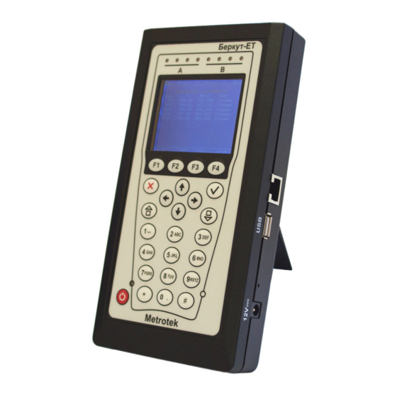
Page 13: Overview
4. Overview Front panel Front panel of Bercut-ET analyzer is shown on the figure 4.1. Figure 4.1. Front panel 1 – LEDs. Three-color LEDs at the top of the front panel provide information about interface state. Bercut-ET. Operations manual... - Page 14 4 – Keyboard. Keys function: — Switch device on/off • To switch device on/off press and hold the button for 1–2 seconds. — Main menu • Press the button to return to the Main menu. — Enter • Bercut-ET. Operations manual...
- Page 15 - - - p q r s - - - t u v - - - w x y z - - - - - - . , : ; - - - - - - Bercut-ET. Operations manual...
-
Page 16: External Connectors
10/100/1000 Mbps) SFP-module connectors SFP-module Remote control connector Ethernet cable (supported rates 10/100 Mbps) Connect to PC via USB cable USB-interface 12 V External power unit connector Power supply unit Connector availability depends on the tester version. Bercut-ET. Operations manual... -
Page 17: Status Bar
• BER — bit error rate test; • PJ — packet jitter analysis; • GEN — test flow generation; • J+G — packet jitter analisys and test flow generation on the same port; • PTH — pass through mode. Bercut-ET. Operations manual... - Page 18 Bercut-ET. Operations manual...
-
Page 19: Analysis. Typical Tasks And Solutions
(throughput, latency, frame loss rate, and back-to-back), this methodology is the de-facto standard for analyzing the Ethernet-network performance. Bercut-ET analyzer supports four standard tests defined by the RFC 2544 methodology. 1. Throughput. This test allows to determine the maximum possible rate for the Ethernet-networks equipment. - Page 20 Ta values. For the current test and tests described further, all steps are performed automatically. At the figures, only one of connection type is shown. For other possible connection schemes please refer to the see section 5.3. Bercut-ET. Operations manual...
- Page 21 90 % of the maximum rate used and then for 80 % of this rate. The trials are continued with 10 % reducing intervals (a finer granularity is supported) until there are two successive trials in which no frames are lost. Bercut-ET. Operations manual...
- Page 22 If the number of forwarded frames is less than the number of transmitted ones, the time of transmission is being reduced and the test is being rerun. Figure 5.4. Back-to-Back Bercut-ET. Operations manual...
-
Page 23: Connecting Device And Starting To Operate
5.3 Connecting device and starting to operate Connecting device and starting to operate 5.3.1 Device connection schemes Figure 5.5. Connection scheme 1 Figure 5.6. Connection scheme 2 Figure 5.7. Connection scheme 3 Bercut-ET. Operations manual... - Page 24 In the case of testing networks/equipment with capability of IP-traffic routing, two device ports are used (fig. 5.7). Packets are rerouted from one port to another via a router. In addition, Bercut-ET can be connected to a network switch as shown on fig. 5.8.
-
Page 25: Rfc 2544. General Settings
• Src IP — source IP address. • Dst IP — destination IP address. Bercut-ET can set up MAC and IP addresses automatically. • To substitute the current MAC address value with the A (B) port MAC address specified in the Information menu, press •... -
Page 26: Setting Up Header (Advanced)
4 and 5 priority values can be used for latency sensitive traffic such as video or speech. Priority values 3–1 are intended for use with different tasks from stream- ing applications to FTP traffic that can cope with possible data loss. Bercut-ET. Operations manual... - Page 27 0010 Maximize reliability Use the value to ensure the packet is delivered without retransmission. 0001 Minimize monetary cost Use the value to minimize the monetary cost of the data delivery. Bercut-ET. Operations manual...
-
Page 28: Rfc 2544. Mpls Settings
Tests ⇒ RFC-2544 ⇒ Setup ⇒ Header ⇒ Advanced ⇒ MPLS. Figure 5.11. Label stack menu • Labels — number of labels (1–3). • Label — label value. • MPLS COS — class of service for datagram. • TTL — time to live for datagram. Bercut-ET. Operations manual... -
Page 29: Test Topology
To perform tests, user can do either of the followings: • select standard sizes of transmitted frames according to the RFC 2544 methodology by pressing (Defaults): 64, 128, 256, 512, 1024, 1280, 1518 bytes; • define any frame size within 64–9600 bytes range. Bercut-ET. Operations manual... -
Page 30: Rfc 2544. Test Parameters Setup
10 ( ), 1 ( ), 0.1 ( ), 0.01 ( ). Lesser resolution value is, the bigger throughput analysis accuracy is. 5.5.2 Latency test settings Figure 5.15. Configuring test settings • Enabled — enable/disable latency analysis. Bercut-ET. Operations manual... -
Page 31: Frame Loss Test Settings
(Manually), Latency test will be performed with physical (L1) rates value defined by user in percent ( ), in kbps ) or in Mbps ( 5.5.3 Frame loss test settings Figure 5.17. Configuring test settings • Enabled — enable/disable frameloss analysis. Bercut-ET. Operations manual... -
Page 32: Back-To-Back Test Settings
• Trial, s — time of the trial performing (within 2–2886 s range) for each of the specified frame sizes. • Rates (L1) — switched to Rates (L1) menu (see fig. 5.16). 5.5.5 Advanced Figure 5.19. Advanced menu Bercut-ET. Operations manual... - Page 33 In accordance with RFC 2544 methodology the wait time is 7000 ms and learn time is 2000 ms. User can specify arbitrary values of wait time within 100–7000 ms range. Learn time must be within 100–2000 ms range. Bercut-ET. Operations manual...
-
Page 34: Rfc 2544. Performing Analysis
The diagram shows throughput values for each specified frame size. The measured throughput value in Frm/s and in percentage (relatively to the specified rate) is displayed on the diagram vertical bars. The results may be displayed in two ways (press button): Bercut-ET. Operations manual... -
Page 35: Latency. Test Results
(percent) measured as a result of the Throughput test. • Graph Figure 5.23. Test results On the diagram, for each of the frame sizes a vertical bar shows the mean value of the latency (ms). Bercut-ET. Operations manual... -
Page 36: Frame Loss. Test Results
(in bytes) and the rate value (percent). • Graph Figure 5.25. Test results On the diagram, for each of the specified frame sizes the relation between frame loss (percent) and the rate (percent) is shown. Bercut-ET. Operations manual... -
Page 37: Back-To-Back. Test Results
On the diagram, for each of the specified frame sizes a vertical bar shows measured value of the time during which the tested equipment was coping with peak load. The count of frames that are transmitted during the test is displayed on the diagram vertical bars. Bercut-ET. Operations manual... -
Page 38: Asymmetric Test
By testing two Bercut-ET should be used: local and remote. On the local device the test parameters are set. The remote device is on the other end of asymmetric channel. -
Page 39: Complex Traffic
After the end of testing the following parameters will be displayed: – specified frame size; – specified rate; – frame loss; – bandwidth. The option is not included into the basic configuration; should be purchased addition- ally. Bercut-ET. Operations manual... - Page 40 – Min — minimal value of latency; – Avg — average value of latency; – Max — maximal value of latency. To switch to the screen that contains information about number of trans- mitted and received frames press button. Bercut-ET. Operations manual...
- Page 41 • Setup — switch to the Setup menu. Figure 5.34. Setup menu – Streams — number of data streams (1–10 ). – Duration — time of data streams generation (1–2886 s). – Topology — switch to the Topology menu. Bercut-ET. Operations manual...
- Page 42 – Header — switch to the Header menu. Figure 5.36. Header menu To select stream number press buttons. Settings cor- respond to one described in the subsection 5.4.1 and 5.4.2. – Frames — switch to the Frames menu. Bercut-ET. Operations manual...
- Page 43 5.8 Complex traffic Figure 5.37. Frames menu Frame size for every stream defines within 64–9600 bytes range. Bercut-ET. Operations manual...
-
Page 44: Complex Traffic. Mpls Settings
Tests ⇒ Complex traffic ⇒ Setup ⇒ Header ⇒ Advanced ⇒ MPLS. Figure 5.39. Label stack menu • Labels — number of labels (1–3). • Label — label value. • MPLS COS — class of service for datagram. • TTL — time to live for datagram. Bercut-ET. Operations manual... -
Page 45: Loopback
• At the Network layer (L3) all incoming packets are being retrans- mitted backward with source and destination IP addresses swapping. Bercut-ET supports substitution of destination and/or source IP ad- dress with user-defined IP address. Both incoming and outgoing traffic statistics are being gathered. -
Page 46: Configuring L2 Loopback
• Swap MAC — enable/disable swapping of destination and source MAC addresses in incoming packets. • Replace MAC — select MAC address substitution mode: – Off — MAC address substitution is disabled; – Source — substitute Source MAC Address value, see fig. 5.43; Bercut-ET. Operations manual... - Page 47 • ID — specify the value that will substitute VLAN ID of an Ethernet frame. • Priority — specify the value that will substitute VLAN priority of an Ethernet frame. Figure 5.42. Dst swapping mode Figure 5.43. Src swapping mode Bercut-ET. Operations manual...
-
Page 48: Configuring L3 Loopback
• Replace — select the mode of ToS swapping: – Off — swapping of Type of Service and Precedence values is dis- abled; – ToS — swap Type of Service values; – Precedence — swap Precedence values; Bercut-ET. Operations manual... - Page 49 • ToS — specify the value that will substitute Type of Service of an Ethernet frame. • Precedence — specify the value that will substitute Precedence of an Ethernet frame. Figure 5.46. Src swapping mode Figure 5.47. Dst swapping mode Figure 5.48. Src+Dst swapping mode Bercut-ET. Operations manual...
-
Page 50: Oam
Loopback mode for the remote end. Both devices should support the IEEE 802.3ah standard. To establish connection between Bercut-ET and remote device via OAM protocol and to switch on Loopback mode it is necessary to execute the fol- lowing actions. - Page 51 – Send loc/rem — transmission of OAMPDU with information about supported operating mode of local and remote devices (with label that means connection establishing possibility); – Send loc/rem ok — receiving OAMPDU with information that operating modes of local and remote devices are compatible; Bercut-ET. Operations manual...
- Page 52 • Var. retrieval — support of reading variables that are used for esti- mation of data link quality. • LB status — Loopback mode state at the remote device. Successful connection will be established only if the remote device supports Remote loopback function. Bercut-ET. Operations manual...
-
Page 53: Discovery
Figure 5.52. Connection diagram In accordance with connection diagram it is possible to switch loopback mode on for several devices Bercut-ET and/or Bercut-ETL in series. The devices may be in the same or in the different subnets. Figure 5.53. ET discovery menu To receive data about remote device and to switch loopback on: •... - Page 54 — switch on loopback at the network layer; • — switch on loopback at the transport layer. • Note: To transmit data UDP protocol is used. Number of server UDP port is 0×8018. Number of client UDP port is 0×8019. Bercut-ET. Operations manual...
-
Page 55: Testing Tcp/Ip
To perform the test it is necessary to execute the following actions: 1. Connect Bercut-ET to network using one port in accordance with con- nection diagram given below. Figure 5.54. Connection diagram 1 Note: you can connect Bercut-ET to network using two ports (see fig. - Page 56 Figure 5.56. Ping menu Functional buttons: • (Start ) — test start; (Statistics) — switch to the Ping statistic screen; • (Setup) — switch to the Ping settings menu. • 3. Set test parameters in the Ping settings menu. Bercut-ET. Operations manual...
- Page 57 • size of ICMP packet; • IP address of a network host that has responded to the request; • packet number; • time between request sending and response receiving. Gateway IP address is set in the Network setup menu Bercut-ET. Operations manual...
-
Page 58: Traceroute
Figure 5.59. Ping test statistics 5.12.2 Traceroute Traceroute utility is used to determine data transmission routes in TCP/IP networks. The utility sends sequence of datagrams to a specified The option is not included in the basic configuration; should be purchased additionally. Bercut-ET. Operations manual... - Page 59 To perform the test it is necessary to execute the following actions: 1. Connect Bercut-ET to network using one port in accordance with con- nection diagram (see fig. 5.54). 2. Switch to the Traceroute menu (see fig. 5.60). Press button (Setup).
-
Page 60: Dns (Dns Lookup)
DNS (Domain Name System) — distributed database that is able to de- termine an IP address of a network host upon a request with the host domain Gateway IP address is set in the Network setup menu Bercut-ET. Operations manual... -
Page 61: Arp Monitor
NS-servers operation. To perform the test it is necessary to execute the following actions: 1. Connect Bercut-ET to network using one port in accordance with con- nection diagram (see fig. 5.54). 2. Switch to the DNS lookup menu (see fig. 5.63). -
Page 62: Tcp-Client
TCP-client is a utility to establish connection with remote network node, to receive data from it and to transmit data to it. TCP-client option allows The option is not included in the basic configuration; should be purchased additionally. Bercut-ET. Operations manual... - Page 63 TELNET protocol. To perform the test it is necessary to execute the following actions: 1. Connect Bercut-ET to network in accordance with connection diagram (see fig. 5.54). 2. Set connection parameters (TCP-client ⇒ Setup ( •...
- Page 64 HTTPGET method. To retrieve this information you need: 1. Enter the file name in File field (see fig. 5.66). 2. Establish connection between Bercut-ET and host. 3. Press button (HTTPGET ). Test result example is shown on the fig. 5.68.
- Page 65 5.12 Testing TCP/IP Figure 5.68. Response example Bercut-ET. Operations manual...
-
Page 66: Pass Through
If transmission rates for port A and port B are different, data loss is possible. Data loss occurs if transmission is carried out from port with greater rate to the one with lesser one. Figure 5.70. Transit menu Bercut-ET. Operations manual... -
Page 67: Cable Diagnostics
To determine cable type it is necessary to execute the following actions. 1. Switch to the Cable test screen. 2. One end of the cable connect to the port A(B) of Bercut-ET, another one — to the port B(A). 3. By pressing... - Page 68 — — — — MDI-X MDI-X crossover MDI-X MDI-X — — — — 10/100 MDI-X straight- MDI-X through — — — — MDI-X straight- MDI-X through — — — — Bercut-ET. Operations manual...
- Page 69 5.14 Cable diagnostics Table 5.5. Cable type analyzing ( continued) crossover MDI-X MDI-X crossover MDI-X MDI-X MDI-X MDI-X MDI-X MDI-X 1000 MDI-X straight- MDI-X through MDI-X MDI-X MDI-X straight- MDI-X through MDI-X MDI-X Bercut-ET. Operations manual...
-
Page 70: Bert
— into Ethernet-frame thus allowing to transmit test packets through a network with both OSI’s second- and third-layer equipment (for exam- ple, network switch, network router). Possible connection schemes are shown on fig. 5.85, 5.86, and 5.87. Figure 5.74. Network layer frame Bercut-ET. Operations manual... - Page 71 • %LOS — ratio of LOS duration to the elapsed time (ET), percentage. • Setup — switch to the BERT Setup menu. To switch to the Results menu press button (Results). For more details see section 5.19. Bercut-ET. Operations manual...
- Page 72 Use the Topology menu to specify receiving and transmitting ports. The same port can be used for both data transmission and receiving (for example, with the Loopback feature). If you use asymmetric test function you must select Remote as receiving/transmitting port (see Bercut-ET. Operations manual...
- Page 73 2e20-1 bit rates up to 72 kbit/s. Error and jitter measurements at bit 2e23-1 rates of 34 368 and 139 264 kbit/s. Errors detection (for higher-speed data 2e29-1 links (transmission rate is over 139 264 2e31-1 kbit/s)). Bercut-ET. Operations manual...
-
Page 74: Bert. Mpls Settings
Figure 5.81. Label stack menu • Labels — number of labels (1–3). • Label — label value. • MPLS COS — class of service for datagram. • TTL — time to live for datagram. Bercut-ET. Operations manual... -
Page 75: Connection Schemes
Figure 5.82. Reception rules menu • Labels — number of labels (1–3). • Label 1, Label 2, Label 3 — label value. 5.15.2 Connection schemes Figure 5.83. Physical layer testing (scheme 1) Figure 5.84. Physical layer testing (scheme 2) Bercut-ET. Operations manual... - Page 76 Analysis. Typical tasks and solutions switch/ router Figure 5.85. Data link/Network layer testing (scheme 1) switch/ router Figure 5.86. Data link/Network layer testing (scheme 2) Figure 5.87. Data link/Network layer testing (scheme 3) Bercut-ET. Operations manual...
-
Page 77: Packet Jitter
(Start ), the measurement of packet jitter for the port which has been specified in the Packet jitter. Setup menu, is started. The feature is not included into basic configuration and should be purchased addition- ally. Bercut-ET. Operations manual... - Page 78 As a result of the test, in the right column the percentage of packets with jitter within corresponding sub-interval limits is displayed. To switch to the Results menu press button (Results). For more details see section 5.19. Bercut-ET. Operations manual...
- Page 79 Figure 5.91. Packet jitter. Setup • Rx port — select a port to measure jitter at. • Threshold, ms — jitter threshold value. • Duration — jitter measurements duration. • Test traffic — switch to the Test traffic menu. Bercut-ET. Operations manual...
-
Page 80: Test Traffic
When generating the test data has been started, all settings in the menu become inaccessible for editing. test data generating port A(B) loopback jitter measuring Figure 5.92. Jitter measurements. Scheme 1 test data generating port B(A) loopback port A(B) jitter measuring Figure 5.93. Jitter measurements. Scheme 2 Bercut-ET. Operations manual... -
Page 81: Test Traffic. Mpls Settings
• RT — time remained to the traffic generating finish. 5.17.1 Test traffic. MPLS settings Label stack and reception rules can be specified in the Label stack menu: Tests ⇒ Test traffic ⇒ Header ⇒ Advanced ⇒ MPLS. Bercut-ET. Operations manual... - Page 82 Analysis. Typical tasks and solutions Figure 5.96. Label stack menu • Labels — number of labels (1–3). • Label — label value. • MPLS COS — class of service for datagram. • TTL — time to live for datagram. Bercut-ET. Operations manual...
-
Page 83: Statistics
• Tx frames — number of transmitted frames. • Rx bytes — number of received bytes. • Tx bytes — number of transmitted bytes. • Rx Kb/s — this field shows the number of kilobits per second received on port. Bercut-ET. Operations manual... -
Page 84: Stats By Frame Types
• Tx — number of transmitted frames. 5.18.3 Stats by frame size Figure 5.99. Stats by frame size • frm size — frame size (in bytes). • Rx — number of received frames. • Tx — number of transmitted frames. Bercut-ET. Operations manual... -
Page 85: Stats By Layer
Figure 5.101. Stats by frame errors • CRC — number of frames with FCS error. • Runt — number of packets less then 64 bytes with correct CRC. • Jabber — number of packets larger then 1518 bytes with FCS error. Bercut-ET. Operations manual... -
Page 86: Saving Test Results
Figure 5.103. Record information menu To save the data: • select a number you want to save the entry with; • press • type in a name for the entry to save; • press • press (Save). Bercut-ET. Operations manual... - Page 87 5.19 Saving test results To load previously saved test results and settings: • select number of an entry; • press (Load ). To delete previously saved test results: • select number of an entry; • press (Delete); • press (Yes). Bercut-ET. Operations manual...
-
Page 88: Network Setup
• MPLS — on/off frames with label transmitting for port A (B) (for LAN port MPLS does not supported). If a value of the MPLS field will be set to Off MPLS field (Interface setup menu) will become inaccessible for editing. Bercut-ET. Operations manual... -
Page 89: Interface Setup
• MPLS — switch to the MPLS. Interface A menu (MPLS. Interface B ). Note: if you use SFP-modules, then the Speed should be always set to the 1Gb/s value. When pressing (Default), the device MAC address value shown in the Information menu is automatically inserted in the field. Bercut-ET. Operations manual... - Page 90 Figure 5.107. Transmission menu • LSR IP — IP address of router interface to which the Bercut-ET is connected. LSR realize label switching. • Rule — on/off the rule for sending packets in the subnet parameters of which defines below.
- Page 91 • MPLS COS — class of service for datagram. • TTL — time to live for datagram. Figure 5.109. Reception rules menu • Labels — number of labels (1–3). • Label 1, Label 2, Label 3 — label value. Bercut-ET. Operations manual...
-
Page 92: Device Setup
• Auto power off — select either of the following values for the tester automatic switching off: Off, 1, 5, or 10 minutes. 5.22.2 Basic settings Figure 5.111. Basic settings menu Bercut-ET. Operations manual... -
Page 93: Information
(Time) to switch to the Uptime menu. Figure 5.113. Uptime menu • Current — device work period between the last switch on and present moment. • Previous — device work period between the previous switch on and switch off. Bercut-ET. Operations manual... -
Page 94: Sfp Information
◦ maximum capacity (mAh), and the charging time (period of time passed after the charging start) in seconds. 5.22.6 Managing options Option is an extra-functionality of the Bercut-ET analyzer that is not bundled in the basic shipment. Bercut-ET. Operations manual... - Page 95 Description TCP/IP network diagnostics (routing, nodes availability, ETIP DNS). ETWEB HTTP-connections testing (requires ETIP option enabled). ETJT Packet jitter measurements. Remote control for the Bercut-ET via TELNET protocol and ETRC WWW-interface. ETMM Complex traffic generating. ETMPLS MPLS support. ETAT Asymmetric test support.
- Page 96 Bercut-ET. Operations manual...
-
Page 97: Remote Control
Terminal mode connection settings 1. Make sure that the device is switched on. 2. Connect Bercut-ET to a USB-port using the USB-cable from the kit. 3. If you use HyperTerminal utility, perform the following steps: • create new connection (File ⇒ New Connection menu);... -
Page 98: Updating Analyzer Software
Attention! False actions during the software update can lead to the device part-malfunctioning which can be repaired in the service- center only. The latest versions of the Bercut-ET software are available for down- loading at http://www.metrotek.spb.ru site. Current software versions are shown in the Information menu (Bercut-ET Settings⇒Information). - Page 99 12V power supply connector on the side panel. 6.1.2.3 Updating file system 1. Connect the Bercut-ET to PC via USB (see section 6.1.1). Check the connection using AT command. 2. Type in ATR command. Select FS image.
-
Page 100: Remote Control Via Telnet
PC all the settings and results of the major tests. To view results, connect to Bercut-ET via A(B) port or the LAN port, and type the IP-address of connected port into the address line of your web- browser. -
Page 101: Screen Shot
6.4 Screen shot Screen shot To get screen shot, connect to Bercut-ET via A(B) port or the LAN port, and type into the address line of your web-browser: http://IP-address_of_connected_port/sshot. Figure 6.2. Screen shot Bercut-ET. Operations manual... - Page 102 Bercut-ET. Operations manual...
-
Page 103: A Ethernet Frame Structure
• Pad — Padding. If the data field is less than 46 bytes, the containing frame is complemented to the minimum allowed length (64 bytes) with the padding field. • Frame Check Sequence — the 4-bytes field contains the checksum. Bercut-ET. Operations manual... - Page 104 0 (null) for Ethernet frames. – VLAN ID — VLAN Identifier (VID) is a 12-bit identifier which is defined in the 802.1Q standard [1]. VID uniquely defines VLAN to which the current frame belongs to. Bercut-ET. Operations manual...
-
Page 105: B Remote Control Commands
Bercut-ET. Operations manual... - Page 106 (Kbps) show bert duration trial duration for BERT bert start start BERT Bercut-ET. Operations manual...
- Page 107 DHCP function is enabled for the show network b dhcp port B show network b ip show IP address of the port B show network b subnetmask show subnet mask for the port B Bercut-ET. Operations manual...
- Page 108 5 text rfc2544 frames 6 text rfc2544 frames 7 text rfc2544 frames 8 text set trial duration for the throughput rfc2544 throughput duration text analysis rfc2544 throughput enabled no/yes enable/disable throughput analysis Bercut-ET. Operations manual...
- Page 109 BERT Packet jitter select port on which jitter measure- jitter port a/b ments will be performed jitter threshold int set threshold (ms) jitter duration hh.mm.ss set measurements duration Bercut-ET. Operations manual...
- Page 110 A select the transmission rate for the gbe b speed automatic/10/100/1000 port B Common commands exit exit from the configuration mode show the list of available commands help Bercut-ET. Operations manual...
-
Page 111: C Specifications And Technical Characteristics
Control interfaces Overall size 200×101×44 mm Weight 0,640 kg Table C.2. Technical capabilities of Bercut-ET Available tests: Throughput, Frame Loss, Back-to- Tests according to RFC 2544 Back, Latency. Frame size: 64, 128, 256, 512, 1024, 1280, 1518 bytes, and user-defined. - Page 112 Specifications and Technical characteristics Table C.2. Technical capabilities of Bercut-ET (continued) Remote control of the analyzer in the following modes: terminal, via TELNET protocol, via WWW-interface. Remote control With remote control running the tests, parameters set- up, getting test results are supported.
-
Page 113: D Troubleshooting
Power supply unit fail- Check and replace if necessary the charged from the exter- ure, broken wire, battery power supply unit or the buttery nal power supply failure Bercut-ET. Operations manual... - Page 114 Bercut-ET. Operations manual...
-
Page 115: Bibliography
[6] RFC 4689, Terminology for Benchmarking Network-layer Traffic Control Mechanisms, S. Poretsky, October 2006. [7] ITU-T O.150 (05/96), General requirements for instrumentation for per- formance measurements on digital transmission equipment. [8] IEEE 802.3ah, Ethernet in the First Mile Task Force. Bercut-ET. Operations manual... - Page 116 83 frame errors, 83 frame size, 82 frame type, 82 ports summary, 81 Test parameters back-to-back, 30 frameloss, 29 latency, 28 throughput, 28 Test results back-to-back, 35 frameloss, 34 latency, 33 Throughput, 17 Traceroute, 56 Bercut-ET. Operations manual...
Need help?
Do you have a question about the Bercut-ET and is the answer not in the manual?
Questions and answers