Table of Contents
Advertisement
Advertisement
Table of Contents

Summary of Contents for Mobile Devices C4DONGLE-3GNAV6
- Page 1 C4DONGLE-3GNAV6 INSTALLATION GUIDE V 1.1 06/12/2016...
-
Page 2: Table Of Contents
Table of contents Preface ............................3 Warnings and notices ....................... 3 1. Hardware features ......................... 4 2. Hardware description ......................5 2.1. External view ........................5 2.2. Internal view ........................5 2.3 OBD connector pin out ....................5 2.4 OBD adapter wires ......................6 3. -
Page 3: Preface
Mobile Devices Ingénierie can in no event be held liable for technical or editorial errors or omissions herein, nor for incidental, special or consequential damages from the furnishing, performance or use of this installation guide. -
Page 4: Hardware Features
1. Hardware features OBD Dongle Performance Processor Atmel - 500MHz 128 Mbytes NAND Flash 256 Mbytes Power supply External power supply 8-32V ● External voltage measurement ● Li-pol battery 450mA.h Communication Modem 3G US Data module (u-blox SARA-U260) GSM 850, PCS 1900 ... -
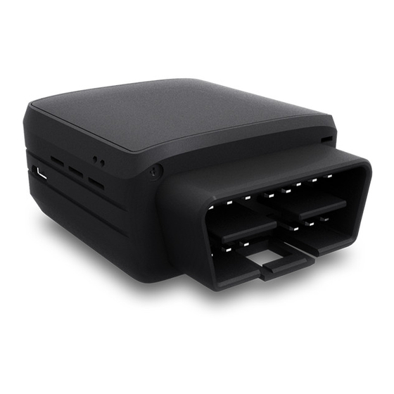
Page 5: Hardware Description
2. Hardware description 2.1. External view ODB connector microUSB connector 2.2. Internal view GSM antenna GPS antenna SIM holder Internal battery* 2.3 OBD connector pin out Pin # Comment J1850+ (PWM/VPW) Chassis ground Signal ground CAN High K line J1850- (PWM) CAN low L line Battery voltage... -
Page 6: Obd Adapter Wires
* Please read warnings section at the beginning of the installation guide 2.4 OBD adapter wires This adapter is only used to connect the OBD to a computer (laptop/desktop). Pin # Wire color Yellow Black Grey Green Blue Violet Orange White... -
Page 7: Preparing/Installing The Device
3. Preparing/installing the device 3.1. Open the device to insert a SIM card... -
Page 8: Properly Close The Device
3.2. Properly close the device First, check that the hole of the electronic card is correctly inserted in the plastic part. If it’s not inserted proceed as shown below. - Page 9 Third, check that the micro USB port is correctly inserted on its place. If it’s not inserted proceed as shown below. Finally, insert the battery and place the screw.
-
Page 10: Install The Obd Dongle
3.3. Install the OBD Dongle Connect the OBD Dongle on your vehicle OBD connector. 4. LED sequences The Dongle has a two-coloured LED, green and red. When both colours are brightened, you can see an orange light. Green LED Red LED Sequence Meaning Sequence... -
Page 11: Fcc Rf Exposure Information (Sar)
-Reorient or relocate the receiving antenna. -Increase the separation between the equipment and receiver. -Connect the equipment into an outlet on a circuit different from that to which the receiver is connected. -Consult the dealer or an experienced radio/TV technician for help. Caution: Changes or modifications not expressly approved by the party responsible for compliance could void the user‘s authority to operate the equipment. -
Page 12: Ised Radiation Exposure Statement
Cet appareil numérique de la classe B est conforme à la norme NMB-003 du Canada. 20253-C4DGL3GV6 9. ISED Radiation Exposure Statement This device is compliance with SAR for general population/uncontrolled exposure limits in ISED RSS-102 and had been tested in accordance with the measurement methods and procedures specified in IEEE 1528 and IEC 62209.
Need help?
Do you have a question about the C4DONGLE-3GNAV6 and is the answer not in the manual?
Questions and answers