Advertisement
Quick Links
FEDERAL COMMUNICATIONS COMMISSION
This equipment has been tested and found to comply with the limits of a Class A digital device, pursuant to Part 15 of the FCC
Rules. These limits are designed to provide reasonable protection against harmful interference when equipment is operated in
a commercial environment. This equipment generates, uses, and can radiate radio frequency energy and, if not installed and
used in accordance with the instruction manual, may cause harmful interference to radio communications. Operation of this
equipment in a residential area is likely to cause harmful interference in which case the user will be required to correct the
interference at his expense.
CE
This equipment has been tested and found to conform to the directives and standards for a Class A Information Technology
Equipment type and for the Commercial Light Industrial equipment class.
INTRODUCTION
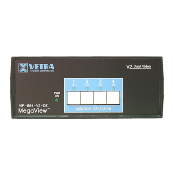
The VIP-804 "MegaView" Video Switches are available as a single, dual, triple, and quad multi head, Integrated Video
Switch with Remote Control, switching from one to up to four monitors between four PC's
The "MegaView" system consists of the following components:
1. One – Video Switch Unit;
2. One – VIP-210 power supply.
Note: The "MegaView" does not come with VGA extension cables. They may be ordered from Vetra separately.
INSTALLATION
There are three main steps to connect the Video Switch:
1. Connect PC's to Switch unit:
Connect the Video outputs of the PC's to the Video Switch using 15 pin HDD15 male/female extension cables. Connect
PC#1's video output to the backpanel connector of the Video Switch marked "TO PC1 MON". Connect PC's #2, #3, and #4
video output's to the appropriate backpanel connector of the Video Switch marked "TO PC2 MON", TO PC3 MON", and "TO
PC4 MON".
Connect PC#1's Monitor A video output to the backpanel connector of the Video Switch marked "PC1 MON A" and connect
PC#1's Monitor B video output to the backpanel connector of the Switch marked "PC1 MON B". For V3 and V4 models
connect PC#1's Monitors C and D video outputs to the back panel connectors of the MegaView marked "PC 1 MON C" and
"PC 1 MON C". Repeat for PC's #2, #3, and #4.
2. Connect a Monitor(s) to the Switch:
Connect the VGA monitor to the 15-pin HDD connector on the backpanel of the Switch marked "MONITOR IN ".
User Instructions for
the VIP- 804 Series "MegaView"
Video Switch
Or in the case of the V2, V3, and V4 series MegaView
Or in the case of the V2, V3, and V4 series of MegaView
275 Marcus Blvd. Ste-J, Hauppauge, NY 11788-2022 USA
Tel: 631.434.3185 Fax: 631.434.3516
www.vetra.com email: sales@vetra.com
Advertisement

Related Manuals for Vetra MegaView VIP-804-V


Summary of Contents for Vetra MegaView VIP-804-V
- Page 1 1. One – Video Switch Unit; 2. One – VIP-210 power supply. Note: The "MegaView” does not come with VGA extension cables. They may be ordered from Vetra separately. INSTALLATION There are three main steps to connect the Video Switch: 1.
- Page 2 Maximum Resolution: up to 1600 x 1200 to 75 Hz MegaView is a trademark of Vetra Systems Corporation Copyright © 1999 - 2008 by Vetra Systems Corporation All Rights Reserved VETRA Systems Corporation 275 Marcus Blvd. Ste-J, Hauppauge, NY 11788-2022 USA Phone: 631.