
Summary of Contents for Microchip Technology SOT23-3
- Page 1 SOT23-3 Voltage Regulator Evaluation Board User’s Guide © 2008 Microchip Technology Inc. DS51785A...
- Page 2 PowerMate, PowerTool, REAL ICE, rfLAB, Select Mode, Total Endurance, WiperLock and ZENA are trademarks of Microchip Technology Incorporated in the U.S.A. and other countries. SQTP is a service mark of Microchip Technology Incorporated in the U.S.A. All other trademarks mentioned herein are property of their respective companies.
-
Page 3: Table Of Contents
Chapter 1. Product Overview 1.1 Introduction ..................... 5 1.2 What is the SOT23-3 Voltage Regulator Evaluation Board? ......5 1.3 What the SOT23-3 Voltage Regulator Evaluation Board kit includes? ..6 Chapter 2. Installation and Operation 2.1 Introduction ..................... 7 2.2 Features ...................... - Page 4 SOT23-3 Voltage Regulator Evaluation Board User’s Guide NOTES: © 2008 Microchip Technology Inc. DS51785A-page iv...
-
Page 5: Preface
• Customer Support • Document Revision History DOCUMENT LAYOUT This document describes how to use the SOT23-3 Voltage Regulator Evaluation Board as a development tool to emulate and debug firmware on a target board. The manual layout is as follows: •... -
Page 6: Conventions Used In This Guide
SOT23-3 Voltage Regulator Evaluation Board User’s Guide CONVENTIONS USED IN THIS GUIDE This manual uses the following documentation conventions: DOCUMENTATION CONVENTIONS Description Represents Examples Arial font: ® Italic characters Referenced books MPLAB IDE User’s Guide Emphasized text ...is the only compiler... -
Page 7: Recommended Reading
Preface RECOMMENDED READING This user's guide describes how to use SOT23-3 Voltage Regulator Evaluation Board. Other useful documents are listed below. The following Microchip documents are available and recommended as supplemental reference resources. • MCP1700A Datasheet, “Low Quiescent Current LDO” (DS-22069) •... - Page 8 SOT23-3 Voltage Regulator Evaluation Board User’s Guide NOTES: © 2008 Microchip Technology Inc. DS51785A-page 4...
-
Page 9: Chapter 1. Product Overview
By soldering the desired device to the evaluation board, the user can easily validate several parameters of the device. 1.2.1 Funtional Blocks The SOT23-3 Voltage Regulator Evaluation Board can be broken up into 3 functional blocks. These blocks are as follows: • Input Capacitance • Ground Current Measurement •... -
Page 10: What The Sot23-3 Voltage Regulator Evaluation Board Kit Includes
This SOT23-3 Voltage Regulator Evaluation Board kit includes: • SOT23-3 Voltage Regulator Evaluation Board (102-00200) • Analog and Interface Products Demonstration Boards CD-ROM includes: - SOT23-3 Voltage Regulator Evaluation Board User’s Guide, (DS51785) © 2008 Microchip Technology Inc. DS51785A-page 6... -
Page 11: Chapter 2. Installation And Operation
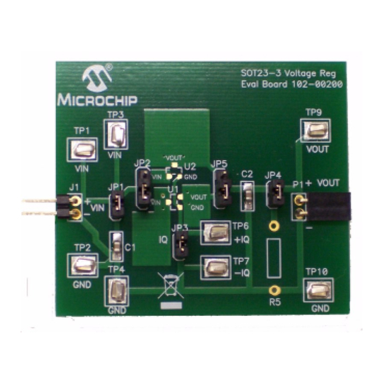
Jumpers have been placed on the board to ease the test of the specific voltage regulator parameters. The SOT23-3 Voltage Regulator Evaluation Board kit comes with a 1 μF ceramic input and output capacitor soldered to the board. The board has two unpopulated resistor locations that may be used for loads. - Page 12 SOT23-3 Voltage Regulator Evaluation Board User’s Guide 2.3.2 Ground Current and Quiescent Current When measuring ground current, jumper JP3 should be removed, otherwise leave jumper JP3 on. To measure ground current, perform the following steps: 1. Add the desired load resistor to R5.
- Page 13 Power Supply Rejection Ratio (PSRR) Power Supply Rejection Ratio tests are performed by removing the input capacitor jumper, JP1, and connecting an appropriate PSRR analyzer to the SOT23-3 Voltage Regulator Evaluation Board. The PSRR analyzer may then sweep the input voltage frequencies and record the corresponding output voltages.
- Page 14 SOT23-3 Voltage Regulator Evaluation Board User’s Guide NOTES: © 2008 Microchip Technology Inc. DS51785A-page 10...
-
Page 15: Appendix A. Schematic And Layouts
SOT23-3 VOLTAGE REGULATOR EVALUATION BOARD USER’S GUIDE Appendix A. Schematic and Layouts INTRODUCTION This appendix contains the following schematis and layouts for the SOT23-3 Voltage Regulator Evaluation Board: • Board - Schematic • Board - Top Silk and Pads • Board - Top Copper •... -
Page 16: Board - Schematic
SOT23-3 Voltage Regulator Evaluation Board User’s Guide BOARD - SCHEMATIC © 2008 Microchip Technology Inc. DS51785A-page 12... -
Page 17: Board - Top Silk And Pads
Schematic and Layouts BOARD - TOP SILK AND PADS © 2008 Microchip Technology Inc. DS51785A-page 13... -
Page 18: Board - Top Copper
SOT23-3 Voltage Regulator Evaluation Board User’s Guide BOARD - TOP COPPER © 2008 Microchip Technology Inc. DS51785A-page 14... -
Page 19: Board - Bottom Copper
Schematic and Layouts BOARD - BOTTOM COPPER © 2008 Microchip Technology Inc. DS51785A-page 15... - Page 20 SOT23-3 Voltage Regulator Evaluation Board User’s Guide NOTES: © 2008 Microchip Technology Inc. DS51785A-page 16...
-
Page 21: Appendix B. Bill Of Materials (Bom)
Connector, Shorting jumper, Tin, 0.100” Sullins STC02SYAN JP3, JP4, RA socket, 0.100 centers, 0.025 sq pins, Sullins PPPC021LGBN-RC 0.070 pcb to pin center height RoHS Compliant Bare PCB, SOT23-3 Voltage Microchip 104-00200 Regulator Evaluation Board Technology Inc. DO NOT POPULATE – –... -
Page 22: Worldwide Sales And Service
Fax: 86-592-2388130 Fax: 886-2-2508-0102 Toronto China - Xian Thailand - Bangkok Mississauga, Ontario, Tel: 86-29-8833-7252 Tel: 66-2-694-1351 Canada Fax: 86-29-8833-7256 Fax: 66-2-694-1350 Tel: 905-673-0699 Fax: 905-673-6509 China - Zhuhai Tel: 86-756-3210040 Fax: 86-756-3210049 01/02/08 © 2008 Microchip Technology Inc. DS51785A-page 18... - Page 23 Mouser Electronics Authorized Distributor Click to View Pricing, Inventory, Delivery & Lifecycle Information: Microchip SOT23-3EV-VREG...
Need help?
Do you have a question about the SOT23-3 and is the answer not in the manual?
Questions and answers