
Subscribe to Our Youtube Channel
Related Manuals for Arbor Technology FPC-9000-V1

Summary of Contents for Arbor Technology FPC-9000-V1
- Page 1 FPC-9000-V1 In-Vehicle Box PC with Intel Xeon ® ® E3/6th&7th Generation Core™ i7/i5/i3 Processors User’s Manual Version 1.0 P/N: 4016900001100P 2020.07...
- Page 2 This page is intentionally left blank. - 2 -...
- Page 3 Revision History Version Release Time Description 2020.07 Initial release - i -...
-
Page 4: Table Of Contents
Contents Contents Revision History ................i Contents ..................ii Preface.................... v Copyright Notice.................. v Declaration of Conformity..............v CE ....................v FCC Class A ................v RoHS ...................vi SVHC / REACH ................vi Important Safety Instructions .............vii Warning .....................viii Replacing Lithium Battery ..............viii Technical Support................viii Warranty ....................ix Chapter 1 - Introduction .............. -
Page 5: Contents
Contents 4.1.5. Install SATA Storage Device ........... 46 4.1.6. Install CFast Card ............50 4.1.7. Install/uninstall SIM Card ..........51 4.2. Ground the Computer ..............52 4.3. Wire DC-in Power Source ............53 4.3.1 Automation Mode ............. 53 4.3.2 Vehicle Application Mode ..........54 4.4. - Page 6 This page is intentionally left blank. - iv -...
-
Page 7: Preface
Preface Preface Copyright Notice All Rights Reserved. The information in this document is subject to change without prior notice in order to improve the reliability, design and function. It does not represent a commitment on the part of the manufacturer. Under no circumstances will the manufacturer be liable for any direct, indirect, special, incidental, or consequential damages arising from the use or inability to use the product or documentation, even if advised of the possibility of such... -
Page 8: Rohs
(PBDE) in electrical and electronic products. Member states of the EU are to enforce by 7/1/2006. ARBOR Technology Corp. hereby states that the listed products do not contain unintentional additions of lead, mercury, hex chrome, PBB or PBDB that exceed a maximum concentration value of 0.1% by weight or for cadmium exceed... -
Page 9: Important Safety Instructions
Preface Important Safety Instructions Read these safety instructions carefully Read all cautions and warnings on the equipment. Place this equipment on a reliable surface when installing. Dropping it or letting it fall may cause damage Make sure the correct voltage is connected to the equipment. For pluggable equipment, the socket outlet should be near the equipment and should be easily accessible. -
Page 10: Warning
Preface Warning The Box PC and its components contain very delicately Integrated Circuits (IC). To protect the Box PC and its components against damage caused by static electricity, you should always follow the precautions below when handling it: Disconnect your Box PC from the power source when you want to work on the inside. -
Page 11: Warranty
Preface Warranty This product is warranted to be in good working order for a period of one year from the date of purchase. Should this product fail to be in good working order at any time during this period, we will, at our option, replace or repair it at no additional charge except as set forth in the following terms. - Page 12 This page is intentionally left blank. - x -...
-
Page 13: Chapter 1 - Introduction
Chapter 1 Introduction Chapter 1 - Introduction - 1 -... -
Page 14: The Computer
Introduction 1.1. The Computer • Fanless Design • Wide Range DC Power Input (9~36V) • Wide temperature range from -40°C to +70°C • 2 x RS-232/422/485 and 8-bit isolated DIO • 4 x 802.3af Gigabit PoE ports by M12 connectors •... -
Page 15: Specifications
Introduction 1.3. Specifications System Intel Xeon E3/6th &7th generation Core™i7/i5/i3 ® ® processor in LGA1151 socket 2 x 260-pin DDR4 SO-DIMM sockets, supporting 2400 MHz Memory SDRAM up to 32GB Chipset Intel C236 ® Graphics Integrated Intel HD Graphics ® 3 x Serial ATA port with 600MB/s HDD transfer rate 1 x Intel WGI219LM GbE controller w/ iAMT 11.0 (except i3) - Page 16 Introduction 2 x mini-PCI Express Slots interconnected with SIM card sockets for optional WiFi/BT/3G/LTE/GPS (PCIex1+USB2.0, Full Size) Expansion Bus 1 x mini-PCI Express slot for optional WiFi/BT/GPS (PCIex1+USB2.0, Half Size) 1 x M.2 (NGFF) B-Key(2242) socket interconnected with SIM card socket for optional LTE module Environmental -40 ~ 60°C, ambient w/ air flow, w/ 35W TDP Core...
-
Page 17: Inside The Package
Upon opening the package, carefully inspect the contents. If any of the items is missing or appears damaged, contact your local dealer or distributor. The package should contain the following items: 1 x FPC-9000-V1 Robust System 1.5. Ordering Information Barebone Fanless In-Vehicle BOX PC for Xeon E3/6th &7th Gen. -
Page 18: Configure-To-Order Service
Introduction 1.5.2. Configure-to-Order Service Make the computer more tailored to your needs by selecting one or more components from the list below to be fabricated to the computer. Xeon™ E3- Intel 6th Gen Xeon™ E3-1268L processor, L2/8M, ® 1268L-V5 2.4G Core i7-7700T Intel... -
Page 19: Chapter 2 - System Overview
Chapter 2 System Overview Chapter 2 - System Overview - 7 -... -
Page 20: Dimensions
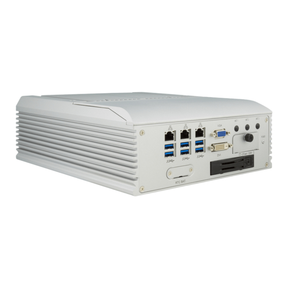
System Overview 2.1. Dimensions 146.00 92.00 92.00 112.00 112.00 146.00 292.00 Unit:mm 2.2. Take A Tour 2.2.1. Front View DVI-D port GbE LAN ports VGA port Antenna holes RTC battery HDD/SSD Tray Power button service window CFast/SIM card window USB 3.0 ports - 8 -... -
Page 21: Rear View
The CPU module supports Windows 10 IOT, 8.1 and 7 To install the drivers, please go to our website at www.arbor-technology.com and download the driver pack from the product page. 2.4. SDK The FPC-9000-V1 SDK is available upon request. If you need the SDK, please contact your local distributor. - 9 -... - Page 22 This page is intentionally left blank. - 10 -...
-
Page 23: Chapter 3 - System Configuration
Chapter 3 System Configuration Chapter 3 - System Configuration - 11 -... -
Page 24: Board Layout
Engine of the Computer 3.1. Board Layout Board Top VGA1 LAN3 LAN2 LAN1 SYSFAN1 JME1 JME2 DGP1 JPIC1 LPT1 CPUFAN1 DIO1 JACCON1 JACCON2 POEOUT1 PWRIN1 - 12 -... - Page 25 Engine of the Computer Board Bottom SIM1 BAT1 USB1 USB2 PCIE1 PWROUT2 PWROUT1 PCIE2 SATA2 SATA1 SCPIN1 SCPOUT1 COM7 COM6 COM5 COM4 - 13 -...
- Page 26 Engine of the Computer JGNDCON3 PWRIN1 JGNDCON1 JGNDCON4 JGNDCON3 JGNDCON4 PWRIN1 JGNDCON2 JCLKCON1 SIM2 SIM2 C6 C3 MBC1 SIM1 SIM1 LAN_POE2 LAN_POE3 LAN_POE1 LAN_POE4 M12_POE2 M12_POE3 M12_POE1 M12_POE4 M12_POE1 M12_POE3 DIO1 M12_AUDIO1 M12_POE2 M12_POE4 - 14 -...
- Page 27 Engine of the Computer Jumpers Label Description ➊ ME FLASH Selection JME1 ➋ CMOS Settings JME2 ➌ Vehicle Acc mode selection JACCON2 ➍ GND Selection JGNDCON1 ➎ GND Selection JGNDCON2 ➏ GND Selection JGNDCON3 ➐ GND Selection JGNDCON4 Connectors Label Description ①...
- Page 28 Engine of the Computer ⑳ Supercapacitor Power Out SCPOUT1 RS-232/422/485 Selectable Serial Port 21 22 COM4, 5 RS-232/422/485 Selectable Serial Port (Reserved) 23 24 COM6, 7 SATA Connector 25 26 SATA1, 2 PWROUT1, 2 SATA HDD Power Connector 27 28 USB 3.0/2.0 Connectors 29 30 USB2, 1...
-
Page 29: Jumpers And Connectors
Engine of the Computer 3.2. Jumpers and Connectors 3.2.1. Jumpers ➊ JME1 Function: ME Flash Selection Jumper Type: 2.54mm pitch, 1x2-pin header Setting: Description Short ME Flash enable Open ME Flash disable (default) ➋ JME2 Function: Clear CMOS Selection Jumper Type: 2.54mm pitch, 1x2-pin header Setting: Description... - Page 30 Engine of the Computer ➍➎➏➐ JGNDCON1, 2, 3, 4 Function: GND Selection Jumper Type: Onboard 2.00mm-pitch 2-pin header Setting: Description Short GND Open N/C - 18 -...
-
Page 31: Connectors
Engine of the Computer 3.2.2. Connectors ① Function Power Button Connector Type: LED tact switch with green and red colors Pin Assignment: Pin Description Description SW1_LED_N SW1_LED_P ② Function: CFast Card Type I/II slot Connector Type: 7+17-pin CFast Card connector consisting of a SATA compat- ible 7-pin signal connector and a 17-pin power and control connector. - Page 32 Engine of the Computer ③ VGA1 Function: Analog RGB & DVI-D Connector Analog RGB Connector Type: Analog RGB (D-Sub 15-pin female type) + DVI-D (DVI-D female connector) DVI-D Pin Assignment: Analog RGB Connector Desc. Desc. Desc. GREEN VDDAT BLUE HSYNC VSYNC VDCLK DVI-D Connector...
- Page 33 Engine of the Computer ④⑤⑥ LAN3, 2, 1 Function: GbE RJ-45 Ethernet Connector & Dual USB3.0 Connectors Connector Type: RJ-45 connector that supports 10/100/1000Mbps fast Ethernet USB3.0 connector Type-A connectors Pin Assignment: The pin assignments conform to the industry standard. 1 2 3 4 1 2 3 4 ⑦...
- Page 34 Engine of the Computer ⑨ CPUFAN1 Function: Fan Power Connector Connector Type: Onbard 2.54mm pitch 1x4-pin one-wall wafer connector Pin Assignment: Pin Description 1 GND 2 +12V 3 RPM 4 Control ⑩ PWRIN1 Function: DC Adapter Power Input Connector Type: 4-pin Terminal block Pin Assignment: Desc.
- Page 35 Engine of the Computer ⑫ JACCON1 Function: Ignition Power Connector Connector Type: Onboard 2x1-pin box connector Pin Assignment: Desc. Acc_ON ⑲ DIO1 Function: Digital IO Connector Connector Type: 2.0mm pitch 2x13 pin box header Pin Assignment: Pin Desc. Desc. DIO0 DIO8 DIO1 DIO9...
- Page 36 Engine of the Computer ⑭ LPT1 Function: On-board Parallel Port Connector Connector Type: 2.00mm pitch 2 x13-pin box header Pin Assignment: Pin Desc. Desc. STB# AFD# ERR# INIT# SLIN# ACK# BUSY SLCT ⑮⑯ MC2, 1 Function: MC1: PCI Express Mini-card Full Size Socket MC2: PCI Express Mini-card Half Size Socket Connector Type: Onboard 0.8mm pitch 52-pin edge card connector Pin Assignment: The pin assignments conform to the industry standard.
- Page 37 Engine of the Computer ⑰ SYSFAN1 Function: Fan Power Connector Connector Type: Onbard 2.54mm pitch 1x4-pin one-wall wafer connector Pin Assignment: Pin Description 1 GND 2 +12V 3 RPM 4 Control ⑱ SIM1 Function: SIM Card Socket Connector Type: 6-pin SIM card socket Pin Assignment: Pin Desc.
- Page 38 Engine of the Computer ⑳ SCPIN2 Function: Supercapacitor power out Connector Type: 2.00mm-pitch 2-pin header Pin Assignment: Desc. +12V COM1, COM2 (Panel label: COM1, COM2) 21 22 Function: RS-232/422/485 Serial Port Connector Type: 1 x9 pin ACES 1.25mm 4-wall connector to 9-pin D-sub male connector RS-232 RS-422...
- Page 39 Engine of the Computer COM1 COM2 COM3, COM4 (Reserved) 23 24 Function: RS-232/422/485 Serial Port Connector Type: 1 x9 pin ACES 1.25mm 4-wall connector RS-232 RS-422 RS-485 Pin Desc. Desc Desc. DCD# DSR# RTS# CTS# DTR# 25 26 SATA1~2 Function: Serial ATA Connector Connector Type: On-board Serial ATA Connector Pin Assignment:...
- Page 40 Engine of the Computer 27 28 PWROUT1, 2 Function: SATA HDD Power Connector Connector Type: 2.54mm pitch 1x4-pin one-wall connector Pin Assignment: Pin Desc. 1 +5V 2 GND 3 GND 4 +12V USB2, 1 29 30 Function: USB 3.0/2.0 Connectors Connector Type: On-board 1.25mm pitch 1x5 pin wafer connector Pin Assignment:...
- Page 41 Engine of the Computer PCIE1 Function: PCIe x4 Slot Pin Assignment: The pin assignments conform to the industry standard. PCIE2 Function: PCIe x16 Slot Pin Assignment: The pin assignments conform to the industry standard. PWRIN1 Function: DC-in Power Receptacle Connector Type: 2.54mm-pitch 4-pin header Pin Assignment: Desc.
- Page 42 Engine of the Computer M12_POE1~4 Function: M12 GbE PoE Connector Connector Type: M12 8-pin DIP 90D Connector Pin Assignment: Description. MDI1+ MDI1- MDI0+ MDI0- MDI2+ MDI2- MDI3+ MDI3- DIO1 Function: 8-pin Digital I/O connector Connector Type: DB-9 male connector Pin Assignment: Description.
- Page 43 Engine of the Computer M12_AUDIO1 Function: M12 Audio Connector Connector Type: M12 4-pin DIP 90D Connector Pin Assignment: CONN M12-4P DIP 90D Description. AGND 41 43 SIM1, 2 Function: NANO SIM card socket Connector Type: 6-pin SIM card socket Pin Assignment: Desc.
- Page 44 Engine of the Computer MBC1 Function: NGFF M.2 B-Key Socket Connector Type: NGFF M.2 B-Key socket for optional LTE module, supporting 22x42 module Pin Assignment: The pin assignments conform to the industry standard. Function: PCI Express Mini-card Full Size Socket Connector Type: Onboard 0.8mm pitch 52-pin edge card connector Pin Assignment: The pin assignments conform to the industry standard.
-
Page 45: Chapter 4 - Installation And Maintenance
Installation & Maintenance Chapter 4 Installation and Maintenance Chapter 4 - Installation and Maintenance - 33 -... -
Page 46: Install Hardware
Installation & Maintenance 4.1. Install Hardware The FPC-9000-V1 is constructed based on modular design to make it easy for users to add hardware or to maintain the computer. The following sections will guide you to the simple hardware installations for the computer. - Page 47 Installation & Maintenance Carefully lift the top cover and then completely part the top cover from the computer. The inside of the computer comes to view. 4.1.1.2. Remove the Bottom Cover The Serial ATA connectors, the power connectors for SATA storage devices, and the internal USB ports are all built on the bottom side of the main board.
-
Page 48: Install Cpu
Installation & Maintenance The bottom of the computer comes to view. 4.1.2. Install CPU Remove the top cover from the computer as described in 4.1.1.2. Remove on page 34. Top Cover Locate the CPU socket on the main board The processor socket comes with a lever to secure the processor. Please refer to the pictures step by step as below and note that the cover of the socket must always be installed during transportation to avoid damage to the socket. - Page 49 Installation & Maintenance - 37 -...
- Page 50 Installation & Maintenance Find the heat sink in the accessory box. Attach the thermal pad to the heatsink, and remove the blue release liner. Thermal pad for PCH chipset Apply the thermal paste to the CPU. Place the heat sink on the CPU and PCH. Make sure that the thermal pad is in complete contact with the PCH chipset and the heat sink is in complete contact with the CPU to avoid overheating problem.
-
Page 51: Install/Uninstall Memory Modules
The main board has two memory module (DIMM) sockets. Increase memory capacity to make programs run faster on the system. The memory module for the FPC-9000-V1’ SO-DIMM sockets should be a 260-pin DDR4 with a “key notch” off the centre among the pins, which enables the memory module for particular applications. - Page 52 Installation & Maintenance The SO-DIMM sockets are vertical type, and each socket has two latches for fixing the memory modules. The memory module can only be installed by one direction due to the notch. Pull back both latches from the socket. the break latch latch...
- Page 53 Installation & Maintenance Vertically plug the memory module to the DIMM socket. “Fully” plug the memory module until both latches auto-lock the memory module in place. Restore the top cover to the computer. To uninstall a DDR4 memory module: Pull back both latches from the SO-DIMM socket. The DDR4 memory module will be auto-released from the socket.
-
Page 54: Install Wi-Fi Module
Installation & Maintenance 4.1.4. Install Wi-Fi Module Remove the top cover from the computer as described in 4.1.1.2. Remove on page 34. Top Cover Locate the PCI Express Mini-card socket for wireless module. Prepare the Wi-Fi module kit. The module is a half-size module of PCI Express Mini-card form factor, with two U.FL connectors, one is “MAIN“, and the other is “AUX“. - Page 55 Installation & Maintenance Have the RF antenna. The antenna has an SMA connector on one end and an MHF connector on the other. SMA connector MHF connector Connect the RF antenna’s MHF connector to the Wi-Fi module’s main connector marked 0. If you are going to connect a secondary antenna, connect it to the connector marked 1.
- Page 56 Installation & Maintenance The module's key notch should meet the connector's break. Press the module down and fix the module in place using one screw. Locate the SMA antenna holes on front panel. Remove the plastic plug to make an antenna hole. Keep the plastic plug for any possible restoration in the future.
- Page 57 Installation & Maintenance Among the screw Remove thread, there is a the nut and flat side. washer. 10. Pull the SMA connector through the above mentioned antenna hole. Note to meet the aforesaid flattened side with the antenna hole's flat side. Arrange the flat side of the SMA connector to meet the flat side of the antenna hole.
-
Page 58: Install Sata Storage Device
Installation & Maintenance 4.1.5. Install SATA Storage Device 4.1.5.1. Install External SATA Storage Device The computer comes with an outside accessible HDD/SSD tray for SATA storage installation. The outside accessible HDD/SSD tray comes with a lock. To eject the tray, use a flat head screwdriver to unlock the tray. Locked Unlocked Press the drive eject button as shown below to eject the HDD/SSD tray. - Page 59 Installation & Maintenance Slide the tray back into the slot. Press the eject button first to further slide in the tray. (Do not press the lever directly.) When the lever returns a little bit, press the lever to completely slide the tray back into the drive bay. ➊...
- Page 60 Installation & Maintenance 4.1.5.2. Install Internal SATA Storage Device Remove the bottom cover from the computer as described 4.1.1.2. Remove the Bottom Cover on page 35. Find the HDD/SSD brackets inside the computer. Loosen and remove the screws as marked in the illustration below. Then dismount the brackets from the computer.
- Page 61 Installation & Maintenance Install the bracket with the storage device back into the computer by refastening the 3 screws. Connect the SATA signal cable and power cable. SATA connector SATA power connector Restore the bottom cover to the computer. - 49 -...
-
Page 62: Install Cfast Card
Installation & Maintenance 4.1.6. Install CFast Card From the front panel of the computer, find the door to the CFast slot. Loosen and remove the screw that locks the door. Once the screw is removed, open the door. The CFast slot then comes to view. -
Page 63: Install/Uninstall Sim Card
CFast card is installed or uninstalled. 4.1.7. Install/uninstall SIM Card This section will use FPC-9000-V1 as the example to guide you through the SIM card installation steps: From the front panel of the computer, find the door to the SIM card slot. -
Page 64: Ground The Computer
Installation & Maintenance To uninstall the SIM card: Loosen and remove the card door screw and open the card door. Push-eject the SIM card. Remove the SIM card. Refasten the screw to close the card door. Note: Make sure to refasten the screw to close the card door each time the SIM card is installed or uninstalled. -
Page 65: Wire Dc-In Power Source
Installation & Maintenance 4.3. Wire DC-in Power Source 4.3.1 Automation Mode Follow the instructions below for connecting the computer to a DC-input power source. Warning Only trained and qualified personnel are allowed to install or replace this equipment. Before wiring, make sure the power source is disconnected. Find the terminal block in the accessory box. -
Page 66: Vehicle Application Mode
Installation & Maintenance captive screw − DC-IN terminal block 4.3.2 Vehicle Application Mode Follow the instructions below for connecting the computer to a vehicle power source. Make sure JACCON2 jumper is open for vehicle power mode. . For vehicle application, DC power Input wiring pin configuration is as below. -
Page 67: Replace Rtc Battery
Installation & Maintenance 4.4. Replace RTC Battery The computer comes with a built-in supercapacitor CMOS so that users can replace RTC battery without losing settings. To replace the RTC battery: Remove the 2 screws that secure the RTC service battery window. Pull out the RTC battery and disconnect the battery cable from its connector on the system board. - Page 68 This page is intentionally left blank. - 56 -...
-
Page 69: Chapter 5 - Bios
Chapter 5 BIOS Chapter 5 - BIOS - 57 -... - Page 70 BIOS The BIOS Setup utility is featured by American Megatrends Inc to configure the system settings stored in the system’s BIOS ROM. The BIOS is activated once the computer powers on. When the computer is off, the battery on the main board supplies power to BIOS RAM.
- Page 71 BIOS Key Commands The BIOS Setup utility relies on a keyboard to receive user’s instructions. Hit the following keys to navigate within the utility and use the utility. Keystroke Function ← → Moves left/right between the top menus. ↓ ↑ Moves up/down between highlight items.
-
Page 72: Main
BIOS 5.1. Main The Main menu features the settings of System Date and System Time and displays some BIOS info. The featured settings are: Setting Description Set the system date. Use Tab to switch between Data elements. Note that the ‘Day’ automatically changes when you set the date. ►... -
Page 73: Advanced
BIOS 5.2. Advanced The featured settings and submenus are: Setting Description CPU Configuration 5.2.1. CPU Configuration on page 5.2.2. SATA and RST Configuration on page SATA And RST Configuration AMT Configuration 5.2.3. AMT Configuration on page Trusted Computing 5.2.4. Trusted Computing on page ACPI Settings 5.2.5. -
Page 74: Cpu Configuration
BIOS 5.2.1. CPU Configuration Setting Description Enabled (default) for Windows XP and Linux (OS optimized for Hyper-Threading Technology) and Hyper-threading Disabled for other OS (OS not optimized or Hyper- Threading Technology). When disabled only one thread per enabled core is enabled. Number of cores to enable in each processor package. - Page 75 BIOS Only available when Intel Speed Step is Enabled. Enable /Disable (default) Turbo Mode (requires Turbo Mode EMTTM enabled, unless max turbo ratio is bigger than 16 - SKL AO W/A. Enable/Disable (default) CPU power management. C States Allows CPU to go to C state when it's not 100% utilized.
-
Page 76: Sata And Rst Configuration
BIOS 5.2.2. SATA and RST Configuration Setting Description Enables (default) / disables SATA device(s). SATA Controller(s) Configures how SATA controller(s) operate. SATA Mode Selection ► Options: AHCI (default) Aggressive LPM Enables / disables (default) PCH to aggressively enter link Support power state. -
Page 77: Amt Configuration
BIOS 5.2.3. AMT Configuration Intel Active Management Technology (Intel AMT) is a hardware-based solution ® ® that uses out-of-band communication for system administrators to monitor and manage the computers and other network equipment by remote control even if the hard drive is crashed, the system is turned off or the operating system is locked. -
Page 78: Trusted Computing
BIOS 5.2.4. Trusted Computing Setting Description Enable (default) or Disable BIOS support for security Security Device Support device. O.S. will not show Security Device. TCG EFI protocol and INT1A interface will not be available. - 66 -... -
Page 79: Acpi Settings
BIOS 5.2.5. ACPI Settings Setting Description Enable ACPI Auto Enables or Disables (default) BIOS ACPI Auto Configuration Configuration Enables (default) or Disables System ability to Enable Hibernation Hibernate (OS/S4 Sleep State). This option may be not effective with some OS. Select ACPI sleep state the system will enter when the SUSPEND button is pressed. -
Page 80: Super Io Configuration
BIOS 5.2.6. Super IO Configuration Setting Description Serial Port 1-2 Configuration Serial Port Enable (default) or Disable Serial Port (COM). Select an optimal setting for Super IO device. ► Serial Port 1 default: IO=3F8h; IRQ=4 Change Settings ► Serial Port 2 default: IO=2F8h; IRQ=3 Select RS-232 (default), RS-422, RS-485, RS-422 Mode Select Termination Resistor or RS-485 Termination Resistor... - Page 81 BIOS Change the printer port mode: ► Options: STD Printer Mode (default) ; SPP Mode; Device Mode EPP-1.9 and SPP Mode; EPP-1.7 and SPP Mode; ECP Mode; ECP and EPP 1.9 Mode; ECP and EPP 1.7 Mode - 69 -...
-
Page 82: Hardware Monitor
BIOS 5.2.7. Hardware Monitor Setting Description CPUFAN SmartFan Function Enables (default) or Disables Smart Fan Temperature 1~4 & RPM Percentage 1~4 CPUFAN SmartFan Auto fan speed control. Fan speed will follow Configuration` different temperature by different PRM 1-100. SYSFAN SmartFan Function Enables (default) or Disables Smart Fan Temperature 1~4 &... -
Page 83: S5 Rtc Wake Settings
BIOS 5.2.8. S5 RTC Wake Settings Setting Description Enable or Disable (default) system wake on alarm event. ► Options available are: Disabled (default): Wake System Fixed Time: System will wake on the hr::min::sec specifiedc. from S5 DynamicTime: If selected, you need to set Wake up minute increase from 1 - 5. -
Page 84: Pci Sybsystem Settings
BIOS 5.2.9. PCI Sybsystem Settings Setting Description Value to be programmed into PCI Latency Timer Register. PCI Latency Timer ► Options: 32 (default), 64, 96, 128, 160, 192, 224 and 248 PCI Bus Clocks. Value to be programmed into PCI-X Latency Timer Register. -
Page 85: Csm Configuration
BIOS 5.2.10. CSM Configuration Setting Description CSM Support Enable (default) or Disable CSM Support. Control the Legacy/UEFI ROMs priority. Boot option filter ► Options: UEFI and Legacy (default), Legacy only and UEFI only Control the execution of UEFI and Legacy PXE OpROM Network Options: Do not launch (default), UEFI and Legacy ►... -
Page 86: Usb Configuration
BIOS 5.2.11. USB Configuration Setting Description Enables/disables legacy USB support. Options available are Enabled (default), Disabled and ► Auto. Legacy USB Support ► Select Auto to disable legacy support if no USB device are connected. ► Select Disabled to keep USB devices available only for EFI applications. - Page 87 BIOS Use this item to set USB mass storage device start unit Device reset time- command time-out. Options available are: 10 sec, 20 sec (default)., 30 sec, ► 40 sec Use this item to set maximum time the device will take before it properly reports itself to the host controller.
-
Page 88: Chipset
BIOS 5.3. Chipset Setting Description System Agent (SA) Configuration Graphics Configuration 5.3.1.1. Graphics Configuration on page PEG port options Enable Root Port: Enable or Disable the root port. Options: Auto (default), Enabled and Disabled. ► PEG Port Configuration Max Link Speed: Configure PEG 0:1:0 Max Speed. Options: Auto (default), Gen1, Gen 2 and Gen3. - Page 89 BIOS USB Configuration 5.3.1.3. USB Configuration on page PCH LAN Controller 5.3.1.4. PCH LAN Configuration on page Specify what state to go to when power is re-applied after a power failure (G3 state). State After G3 ► Options available are Power On (default), Power Off and Last State.
- Page 90 BIOS 5.3.1.1. Graphics Configuration Setting Description Select the Graphics device which will be activated as Primary Display. Primary Display Options available are Auto (default), IGFX, PEG ► and PCI Enables/disables the IGD. Internal Graphics ► Options available are Auto (default), Disabled, and Enabled.
- Page 91 BIOS Select the DVMT 5.0 Pre-allocated (Fixed) Graphic DVMT Pre-Allocated Memory size used by the Internal Graphic Device. ► 32M is the default. Select the DVMT 5.0 Total Graphic Memory size used DVMT Total Gfx Mem by the Internal Graphic Device. ►...
- Page 92 BIOS 5.3.1.3. USB Configuration Setting Description Options to disable Compliance Mode. Default is XHCI Disable Compliance FALSE (default) to not disable Compliance Mode. Mode Set TRUE to disable Compliance Mode. xDCI Support Enable/disable (default) xDCI (USB OTG Device). Selectively enable/disable (default) the USB Port Disable Override corresponding USB port from reporting a device connection to the controller.
- Page 93 BIOS 5.3.1.4. PCH LAN Configuration Setting Description Enabled (default) / disabled onboard NIC. If enabled, “Wake on LAN” option will be available to PCH LAN Controller enable (default) / disable integrated LAN to wake the system. (The Wake On LAN cannot be disabled if ME is on at Sx state.) Enable (default) or disable integrated LAN to wake Wake on LAN Enable...
-
Page 94: Security
BIOS 5.4 Security Setting Description To set up an administrator password: Select Administrator Password. Administrator An Create New Password dialog then pops up onscreen. Password Enter your desired password that is no less than 3 characters and no more than 20 characters. Hit [Enter] key to submit. -
Page 95: Boot
BIOS 5.5. Boot Setting Description Set how long to wait for the prompt to show for entering BIOS Setup. Setup Prompt Timeout ► The default setting is 1 (sec). ► Set it to 65535 to wait indefinitely. Sets whether to enable or disable the keyboard’s Bootup NumLock State NumLock state when the system starts up. -
Page 96: Save & Exit
BIOS 5.6. Save & Exit Setting Description Save Changes Saves the changes and quits the BIOS Setup utility. and Reset Discard Changes Quits the BIOS Setup utility without saving the change(s). and Exit Restores all settings to defaults. Restore Defaults ►...
Need help?
Do you have a question about the FPC-9000-V1 and is the answer not in the manual?
Questions and answers