
Related Manuals for TESSERA CF-850/F1KM-176-S

Summary of Contents for TESSERA CF-850/F1KM-176-S
- Page 1 CF-850/F1KM-176-S Hardware Manual Date published: May 2018 (1st Edition) Tessera Technology Inc. TS-TUM06992 - 1 -...
- Page 2 Tessera Technology Inc. products listed in this document or any other liability arising from the use of such products. No license, express, implied or otherwise, is granted under any patents, copyrights or other intellectual property rights of Tessera Technology Inc.
-
Page 3: Table Of Contents
TABLE OF CONTENTS INTRODUCTION ......................... 4 FEATURES........................... 5 CAN ............................. 6 ........................9 ERIAL SELECT 2.2.1 LCD ........................... 11 2.2.2 RS-232C ........................14 2.2.3 USB Serial Conversion .................... 15 2.2.4 LIN ..........................16 ........................17 WITCH ..........................18 OLUME ..........................19 OWER ........................ -
Page 4: Introduction
1 Introduction In this document, features and hardware specifications of CF-850/F1KM-176-S, which the 32-bit single-chip microcomputer RH850/F1KM-S4, RH850/F1K and RH850/F1L from Renesas Electronics Corporation is mounted, are described. - 4 -... -
Page 5: Features
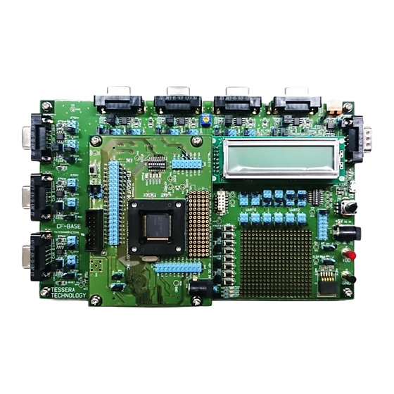
2 Features CAN x 8ch RS-232C Volume Power Serial select CPU Board Push Switch - 5 -... -
Page 6: Can
The CAN controller of the microcomputer is connected to the CAN FD transceiver (TJA1044GT). It supports CAN physical layer. Also, CAN bus signal is connected to DSUB 9pin female connector. CAN 7 CAN 3 CAN 2 CAN 1 CAN 0 CAN 4 CAN 5 CAN 6... - Page 7 Following table shows the connection of RH850/F1KM. - 7 -...
- Page 8 JP5, JP9, JP13, JP17, JP21, JP25, JP29 and JP14(CPU Board) are termination resistor connect. Open or short these as needed. CAN 0, 1, 2, 3, 4, 5, 6, 7 DSUB Termination resistor Connector Pin Number Signal Name JP5 : CAN 0 N.C.
-
Page 9: Serial Select
Serial select It can be connected by selecting the microcomputer's UART terminal to "LCD", "RS-232C", "USB Serial Conversion", and "LIN". JP33, JP35, JP37, JP39, JP41, JP43 JP32, JP34, JP36, JP38, JP40, JP42 The terminals for using UART can be selected by jumpers. P10_10/TAUD0I14/TAUD0O14/R LIN 30TX/ENCA0E1/PWGA7O/CSIH0CSS1/MEMC0AD4/CXPI0TX/TAUJ3I3/TAUJ3O3 JP32... - Page 10 Connection diagram JP32 JP33 UART0_TXD From CPU Port UART_LCD_TXD From CPU Port UART_USB_TXD From CPU Port UART_RS_TXD UART_LIN_TXD JP34 JP35 UART0_RXD From CPU Port UART_LCD_RXD From CPU Port UART_USB_RXD From CPU Port UART_RS_RXD UART_LIN_RXD JP36 JP37 UART1_TXD From CPU Port From CPU Port From CPU Port JP38...
-
Page 11: Lcd
2.2.1 LCD Words can be displayed on LCD panel by sending data to UART that is connected to LCD. "Binary mode" to display hexadecimal and "ASCII mode" to display ASCII characters can be selected by the DIP switch (SW1). Initial screen displays when you press the reset switch on CPU board. Adjust LCD Contrast UART Communication Specifications ・... - Page 12 Binary Mode 2 (SW1_1:ON, SW1_2:OFF, SW1_3:ON) It displays the hexadecimal data as sent without entering space between 1Byte data. It can display 16Byte in 1 screen. It scrolls 1 line when it received 17Byte of data. (example) URTH?TX = 0x01; TXWait(); URTH?TX = 0x02;...
- Page 13 ASCII Mode Ver.2 (SW1_1:OFF, SW1_2:Any, SW1_3:Any) It displays the characters as sent. It can display 16 characters in 1 line. It scrolls 1 line when it received 17th character or linefeed code (0x0D: \r ). URTH?TX = ‘F’; TXWait(); (example) URTH?TX = ‘l’;...
-
Page 14: Rs-232C
2.2.2 RS-232C UART that is connected to "RS-232C" can send and receive signals with the RS-232C level of D-SUB9 pin connector. Use a cross cable when you connect to PC. RS-232C RS-232C D-SUB Connector Pin Number Signal N.C. N.C. N.C. RTS(N.C.) CTS(N.C.) N.C. -
Page 15: Usb Serial Conversion
2.2.3 USB Serial Conversion UART that is connected to "USB serial conversion" can communicate with the COM port of PC through USB controller (FT230). If the USB driver is a PC connected to the Internet, the latest driver is automatically installed by "Windows Update". -
Page 16: Lin
2.2.4 LIN The UART connected to "LIN" is connected to the LIN compatible transceiver (TJA1020T) and corresponds to the physical layer of LIN. JP45 JP44 Default setting JP44: Open JP45: Short (LIN Master) CN3 : IL-G-3P-S3L2-SA (JAE) Function JP44 short circuit output +12V JP45 Function Short... -
Page 17: Push Switch
Push Switch 4 interrupt signals can be connected to microcomputer's interrupt terminals. The signal can be set to High by pressing H button, and to Low by pressing L button. It becomes High by reset signal of the CPU. Also, it has chattering prevention circuit. JP46 SW_NMI JP47... -
Page 18: Volume
Volume It can output variable voltage (0V-IO voltage) to A/D terminal of CPU by variable resistor of 10KΩ. JP48 JP48 AP0_0/ADCA0I0 AP0_1/ADCA0I1 AP0_2/ADCA0I2 AP0_3/ADCA0I3 AP0_4/ADCA0I4 9-10 AP0_5/ADCA0I5 11-12 AP0_6/ADCA0I6 13-14 AP0_7/ADCA0I7 15-16 - 18 -... -
Page 19: Power
Power Connect bundled AC adapter (+5V) to AC Jack. You do not need to connect to the AC Jack on the CPU board. Using the regulator from the power supplied from here, + 12V and + 3.3V are also generated. AC Jack JP2 : 5V JP3 : 3.3V... -
Page 20: Cpu Board
CPU Board "EB-850/F1KM-176-S" is mounted on the CPU board Power Check pin Switch & LED Filter Clock Debug Connector Reset Switch Check pin Check pin - 20 -... -
Page 21: Power
2.6.1 Power There is a jumper pin for measuring the current when you use only CPU board itself. CN9 : AC Jack Select Note Connect ammeter to check the current Short Operation voltage is 5V. Operation voltage is 3.3V. (Only when CF-BASE board is connected) 2.6.2 CPU For "EB-850/F1KM-176-S", only socket is mounted. -
Page 22: Clock
2.6.3 Clock For the X1 and X2 of the CPU, 16MHz crystal oscillator (Y1) is mounted on the socket. For the XT1 and XT2 of the CPU, 32.768KHz crystal oscillator (Y2) is connected. 2.6.4 Reset CPU can be reset by pressing the Reset switch (SW2). As a reset input method to the CF-BASE board, it is possible to select either the reset switch (SW 2) or press the CPU port terminal (F1L: P0_0 or F1K: P8_6) with a jumper pin. -
Page 23: Switch & Led
2.6.5 Switch & LED They are connected to port terminals of the CPU. LED1 LED2 LED3 LED4 Power LED ・ P8_12, P10_3, and P8_5 can be used for the switch inputs. It connects the pull-up resistor with built-in CPU. Set the switch to OFF to read High and to ON to read Low. -
Page 24: Debug Connector
2.6.6 Debug Connector "PG-FP5" of "E1 emulator" corresponding to Low Pin Debug Interface (4-pin) or a flash programmer is connectable with CN6. Signal Number Debugger Writer DCUTCK JP0_2 ← DCUTRST FLMD0 ← DCUTDO JP0_1 N.C. DCUTDI JP0_0 ← DCUTMS N.C. DCUTRDY ←... -
Page 25: Filter Socket
2.6.7 Filter socket Filters can be implemented to A/D input terminals. Connects (CN1, CN2) are connected through the sockets as illustrated below. Therefore, please make sure you connect resistor between the socket 4pin and 5pin when you use A/D terminal. Socket Connector Socket... -
Page 26: Device Select
2.6.9 Device Select Please set the jumper pin according to the device to be mounted on the socket. JP10 13pin 14pin 73pin 72pin 113pin 114pin RH850/F1KM capacitor capacitor RH850/F1K RH850/F1L P11_13 P11_14 P1_6 P1_7 P9_5 P9_6 3 CPU Terminal Connection List Please download the Excel file from the web described in the document attached to the product.
Need help?
Do you have a question about the CF-850/F1KM-176-S and is the answer not in the manual?
Questions and answers