
Summary of Contents for MITECH MT600
- Page 1 Mul-ti Mode Ultrasonic Thickness Gauge MT600 User’s Manual MITECH CO., LTD. www.ponpe.com www.mitech-ndt.com...
-
Page 2: Table Of Contents
sale@ponpe.com CONTENTS 1 Overview..............................4 1.1 Product Features..........................4 1.2 Measuring Principle...........................4 1.3 Specifications............................. 4 1.4 Transducer Technical Parameters....................5 1.5 Configuration............................6 1.6 Operating Conditions........................6 2 Structure Feature............................6 2.1 Main Screen............................7 2.2 Keypad Definitions..........................7 3 Test Preparation............................8 3.1 Transducer Selection........................ - Page 3 sale@ponpe.com ponpe.com 6. Measuring Technologies........................21 6.1 Measuring Method.......................... 21 6.2 Wall Measurement.......................... 21 7 Servicing..............................22 8 Transport and Storage........................... 22 Appendix A Sound Velocities........................23 Appendix B Applications Notes......................24 User Notes..............................26...
-
Page 4: Overview
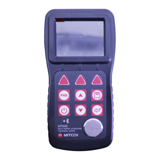
1 Overview The model MT600 is a multi-mode ultrasonic thickness gauge. Based on the same operating principles as SONAR, the instrument is capable of measuring the thickness of various materials with accuracy as high as 0.1/0.01 millimeters. The multi-mode feature of the gauge allows the user to toggle between pulse-echo mode (flaw and pit detection), and echo-echo mode (eliminate paint or coating thickness). -
Page 5: Transducer Technical Parameters
ponpe.com sale@ponpe.com Coupling status indicator showing the coupling status. Units: Metric and Imperial unit selectable. Battery information indicates the rest capacity of the battery. Auto sleep and auto power off function to conserve battery life. USB2.0 communication port ... -
Page 6: Configuration
sale@ponpe.com 1.5 Configuration Table 1.2 Instrument Configurations Item Qty. Note Standar Main body d Config. Probe P5EE(5MHz) Couplant Instrument Case Operating manual Alkaline battery AA size Optional Probe N02 (2.5MHz) Config. Probe N05/90°(5MHz) See Table1.1 Probe N05 (5MHz) Probe N07(7MHz) Probe HT5(5MHz) Data Pro Software USB Cable... -
Page 7: Main Screen
sale@ponpe.com ponpe.com 2.1 Main Screen Mode: "E-E" indicating the instrument work in the Echo-Echo mode; "P–E” indicating it work in the Pulse-Echo mode; Probe: Probe selection Velocity: Sound velocity Battery: Indicating the rest capacity of the battery. Thickness: Last test result Unit: mm or inch Diff value: Differential result when working in diff mode. -
Page 8: Test Preparation
sale@ponpe.com Bluetooth role LED status Bluetooth status Host mode Fast glittering (150 ms Searching and on, 150 ms turn off) connecting Fast glittering 5 times connecting and then turn off after 2 seconds Always on Connected Slave mode Slow glittering (800 ms connecting on, 800 ms turn off) Always on... -
Page 9: Condition And Preparation Of Surfaces
ponpe.com sale@ponpe.com that works well for a given job. The transducer is the “business end” of the instrument. It transmits and receives ultrasonic sound waves that the instrument uses to calculate the thickness of the material being measured. The transducer connects to the instrument via the attached cable, and two coaxial connectors. When using transducers, the orientation of the dual coaxial connectors is not critical: either plug may be fitted to either socket in the instrument. -
Page 10: Connecting The Probe
sale@ponpe.com The battery compartment is situated at the instrument back. The cover is fastened with two screws. To insert the batteries: Loosen the two screws of the battery cover. Lift the cover off upward. Insert the batteries into the battery compartment. ... -
Page 11: Operations
ponpe.com sale@ponpe.com memories. Pressing any key or performing a measurement sets the unit back to run state and the brightness is tuned back. Power off state – After 2 minutes (default setting) the instrument changes from standby state to power off state. The main unit and the display is switched off and consumes almost no energy. Pressing any key will stop the unit entering power off state while it prompts out “Idle Timeout!”... -
Page 12: Sound Velocity Calibration
sale@ponpe.com Press the key to activate the probe zero mode, as right figure. Apply a single droplet of ultrasonic couplant to the face of the metal probe-disc. Press the transducer against the probe disc, making sure that the transducer sits flat against the surface. - Page 13 ponpe.com sale@ponpe.com 5.4.2 Calibration to a known thickness Note: This procedure requires a sample piece of the specific material to be measured, the exact thickness of which is known, e.g. from having been measured by some other means. Perform a Probe-Zero on the standard 4.00 mm disc. Apply couplant to the sample piece.
-
Page 14: Making Measurements
sale@ponpe.com Calibration. Repeat Step 2 to Step 6 on the second calibration point. Finally press the /F3 to complete Two Point Calibration procedure. The gauge is now ready to perform measurements within this range. 5.5 Making Measurements When the tool is displaying thickness measurements, the display will hold the last value measured, until a new measurement is made. -
Page 15: View Mode Setting
sale@ponpe.com ponpe.com 5.6 View Mode Setting Three view modes can be selected show measured value: Normal Mode, Scan Mode and Diff Mode. Normal Mode. As shown in right figure, it shows the last test thickness value. Scan Mode. Besides the last test thickness value, it also shows the minimum thickness value and the... -
Page 16: Limit Setting
sale@ponpe.com Press F1/F2 move the highlight cursor; Press arrow keys increase/decrease values. Press or F3 key to confirm the setting. Press key to cancel the change and exit. 5.8 Limit Setting gauge, test results beyond the limits will be displayed with red color alarm user. - Page 17 ponpe.com sale@ponpe.com Activate Memory Manager dialog as right figure. Press to move the cursor; Press or F3 key to open the View Record Data dialog, next figure. Press to move the cursor desired record. Press F3 to delete the focused record. Press F2 to clear all the records of this group.
-
Page 18: Key Sound Setting
sale@ponpe.com 5.11 Key Sound Setting Key sound can be configured to on or off. When the key sound is set to on, the buzzer inside the main unit would make a short audible alarm while press the key each time. 5.12 Warn Sound Setting Warning sound can be configured to on or off. -
Page 19: Changing Unit System
sale@ponpe.com ponpe.com will forbid main unit switching automatically into power off state. Note: If the voltage of the battery is too low, the LCD screen will show “Battery Exhausted!”, then power off automatically. 5.16 Changing Unit System The instrument supports both metric and imperial unit systems. -
Page 20: Product Information
sale@ponpe.com 5.19 Product Information Information concerning the instrument model, software version serial number of the main unit is displayed. Press , F1 or F3 key to close the dialog box. 5.20 Reset System In case the instrument can no longer be operated, or you need to make a basic initialization (factory setting), you can reset the instrument to original. -
Page 21: Usb Communication
sale@ponpe.com ponpe.com function module will be automatically shut off to save power. Print stored data group via Bluetooth. memory manager dialog box, select “print” will print selected data group. Select “Print All” will print data groups stored inside the instrument. You can also print out the test result directly after each test. -
Page 22: Servicing
sale@ponpe.com diameter is smaller, you should measure in both directions and the minimum value is thickness value. 7 Servicing When the gauge appears some other abnormal phenomena, please do not dismantle or adjust any fixedly assembled parts. Fill in and present the warranty card to us. The warranty service can be carried on. -
Page 23: Appendix A Sound Velocities
ponpe.com sale@ponpe.com Appendix A Sound Velocities Material Sound Velocity in/µs Aluminum 0.250 6340-6400 Steel, common 0.233 5920 Steel, stainless 0.226 5740 Brass 0.173 4399 Copper 0.186 4720 Iron 0.233 5930 Cast Iron 0.173-0.229 4400-5820 Lead 0.094 2400 Nylon 0.105 2680 Silver 0.142 3607... -
Page 24: Appendix B Applications Notes
sale@ponpe.com Appendix B Applications Notes Measuring pipe and tube When measuring a piece of pipe to determine the thickness of the pipe wall, orientation of the transducers is important. If the diameter of the pipe is larger than approximately 4 inches, measurements should be made with the transducer oriented so that the gap in the wearface is perpendicular (at right angle) to the long axis of the pipe. - Page 25 sale@ponpe.com ponpe.com Measuring through paint & coatings Measuring through paints and coatings are also unique, in that the velocity of the paint/ coating will be significantly different form the actual material being measured. A perfect example of this would be a mild steel pipe with approximately 0.6mm of coating on the surface. Where the velocity of the pipe is 5920m/s, and the velocity of the paint is 2300m/s.
-
Page 26: User Notes
Warranty : The product is guaranteed for one year since purchased. Log www.mitech-ndt.com or follow our company official public platform to register for maintenance. Please fill the blanks as required, if the product is not registered for maintenance, it will follow the date of manufacturer.
Need help?
Do you have a question about the MT600 and is the answer not in the manual?
Questions and answers