
Summary of Contents for RetroSound Stereo Phonic
- Page 1 3-Channel Power Amplifier User’s Manual Version 1 MOD E RN SOUND FOR YOUR CLASSIC www.r et rom anu fact u r i ng .c o m...
-
Page 2: Table Of Contents
TABLE OF CONTENTS WELCOME WHAT’S IN THE BOX PRECAUTIONS POWER AND GROUND CONNECTIONS MOUNTING THE AMPLIFIER WIRING DIAGRAM CONTROL PANEL LAYOUT TROUBLESHOOTING SPECIFICATIONS WARRANTY... -
Page 3: Welcome
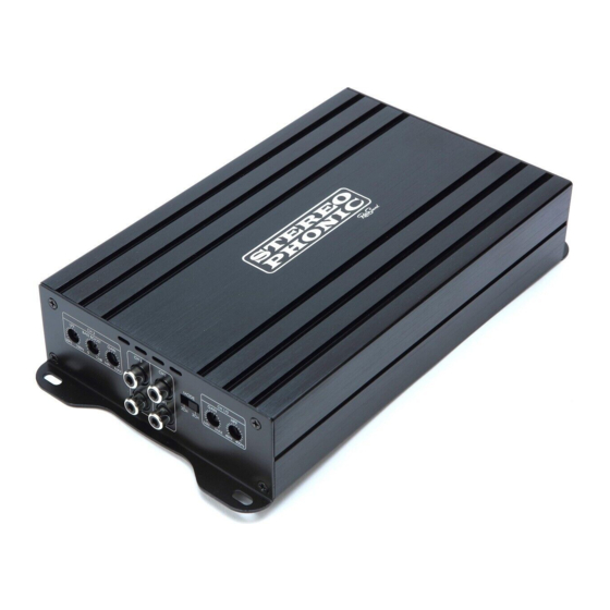
WELCOME Thank you for purchasing a RetroSound Stereophonic 3-channel ® power amplifier. This unique 3-channel amplifier has two 65 watt full-range front channels for mids and highs, plus a 170 watt mono channel for a subwoofer, so a complete audio system can be built using a single amplifier. -
Page 4: What's In The Box
WHAT’S IN THE BOX Stereophonic Amplifier Mounting Hardware and Tools... -
Page 5: Precautions
PRECAUTIONS This owner’s manual provides only general installation and operating instructions. It does not cover every possible installation application. If you have any reservations about installing the amplifier, contact an authorized RetroSound dealer, or contact ® technical support at tech@retromanufacturing.com. - Page 6 PRECAUTIONS • Turn off all stereo devices before you begin. • Disconnect the negative (-) battery terminal from your vehicle’s battery. NOTE: check your vehicle’s owner’s manual before disconnecting the battery. On some newer vehicles, disconnecting the battery may require entering an anti-theft code upon reconnecting the battery and/or may require resetting the vehicle’s on-board computer.
-
Page 7: Power And Ground Connections
POWER AND GROUND CONNECTIONS Stereophonic is designed to work within a range of 12 volts to 14.4 volts DC. Before connecting any wiring, use a multi-meter to test the vehicle’s electrical system for adequate power supply. First, check the voltage at the positive (+) battery terminal with the ignition in the off position. -
Page 8: Mounting The Amplifier
MOUNTING THE AMPLIFIER It is best to mount the amplifier in a location that allows air to freely circulate around it and allows access to the end panel controls for adjustments. Although both thermal and overload protection are built in, if the amplifier overheats it will reduce its power output to maintain operation. -
Page 9: Wiring Diagram
WIRING DIAGRAM STANDARD WIRING RCA CONNECTIONS (3-CHANNEL CONFIGURATION) CH 3 CH 1/2 CH 3 CH 1 BASS BOOST GAIN GAIN MODE 50Hz 250Hz 12dB MIN MAX MIN MAX 40Hz 400Hz CH 2 Copyright © 2017 Retro Manufacturing, LLC... - Page 10 STANDARD WIRING WIRING DIAGRAM POWER AND SPEAKER CONNECTIONS - STANDARD Left Right Speaker Speaker (4 ohm) (4 ohm) Subwoofer (2 or 4 ohm) 30 amp fuse (not included) Place fuse as close to terminal as possible 8 -10 gauge Battery +12 volt constant to battery 16-18 gauge...
- Page 11 BRIDGED WIRING WIRING DIAGRAM POWER AND SPEAKER CONNECTIONS - BRIDGED Subwoofer Subwoofer (2 or 4 ohm) (2 or 4 ohm) 30 amp fuse (not included) Place fuse as close to terminal as possible 8 -10 gauge Battery +12 volt constant to battery 16-18 gauge +12 volt turn-on lead...
-
Page 12: Control Panel Layout
CONTROL PANEL LAYOUT CH 3 CH 1/2 CH 3 CH 1 BASS BOOST GAIN GAIN MODE 50Hz 250Hz 12dB MIN MAX MIN MAX 40Hz 400Hz CH 2 LPF (Low Pass Filter) The LPF (adjustable between 50Hz and 250Hz) filters out frequencies above the designated setting on the amplifier while attenuating frequencies below that setting. - Page 13 CONTROL PANEL LAYOUT Failure to follow these steps could result in damaged speakers and/or amplifier. Mode The Mode control switch toggles the input mode of the amplifier between 2 channel and 3 channel operation. • When set to 2CH, only input channels 1 and 2 will be active. •...
-
Page 14: Troubleshooting
TROUBLESHOOTING PROBLEM SOLUTION Green Power LED does not turn on • Check to ensure that the Battery (+) (12 volt constant) wire has 12 to 14.4 volts. • Check to ensure that the amplifier turn-on lead has 12 volts. • Check the fuse at bottom of the amplifier. -
Page 15: Specifications
SPECIFICATIONS Due to continuing improvements, specifications are subject to change without notice. STEREOPHONIC SPECIFICATIONS Full-Range Power Output @ 4 ohms 65 watts RMS x 2 channels @ 4 ohms Subwoofer Power Output @ 4 ohms 170 watts RMS x 1 channel @ 4 ohms Full-Range Power Output @ 2 ohms 90 watts RMS x 2 channels @ 2 ohms Subwoofer Power Output @ 2 ohms... -
Page 16: Warranty
WARRANTY If your unit does not work properly because of a defect in materials or workmanship, Retro Manufacturing, LCC (collectively referred to as “the warranter”) at its option will either (a) repair your unit with new or refurbished parts, or (b) replace it with new or refurbished unit. - Page 17 INSTALLATION NOTES Copyright © 2017 Retro Manufacturing, LLC...
- Page 18 INSTALLATION NOTES...
- Page 19 INSTALLATION NOTES Copyright © 2017 Retro Manufacturing, LLC...
- Page 20 MODERN SOUND FOR YOUR CLASSIC Retro Manufacturing, LLC, 7470 Commercial Way, Henderson, NV 89011 p) 888.325.1555 | f) 702.483.2229 | www.retromanufacturing.com...
Need help?
Do you have a question about the Stereo Phonic and is the answer not in the manual?
Questions and answers