
Summary of Contents for RKI Instruments SP-220 TYPEH2
- Page 1 Portable Gas Leak Detector SP-220 Series TYPE H2 Operating Manual Part Number: 71-0420 Revision: A Released: 4/9/19...
-
Page 2: Table Of Contents
Contents 1. Outline of the Product ............................. 3 Preface ................................3 Purpose of use ..............................3 Definition of DANGER, WARNING, CAUTION and NOTE ................3 How to check the standards and explosion-proof specifications ..............3 2. Important Notices on Safety ........................... 5 2-1. -
Page 3: Outline Of The Product
Outline of the Product Preface Thank you for choosing our portable gas leak detector SP-220 series (hereinafter referred to as the detector). Please check that the model number of the product you purchased is included in the specifications on this manual. This manual explains how to use the detector and its specifications. - Page 4 specifications The detector has different specifications depending on the standards or explosion-proof certification type. Check the specifications of the product you have before use. See the Declaration of Conformity at the end of this operating manual for CE marking specifications. For the product specifications, check the nameplate attached to the product shown in the following figure.
-
Page 5: Important Notices On Safety
Important Notices on Safety To maintain the performance and use the detector safely, observe the following instructions of DANGER, WARNING, and CAUTION. 2-1. Danger cases DANGER About use • While conducting measurement in a manhole or confined space, do not lean over or look into the manhole or closed space. -
Page 6: Warning Cases
2-2. Warning cases WARNING Sampling point pressure • The concentration meter is designed to draw gases under the atmospheric pressure. If excessive pressure is applied to the gas inlet and outlet of the detector, measured gases may leak out from its inside and may cause dangerous conditions. Be sure that excessive pressure is not applied to the detector’s inlet or outlet during use. -
Page 7: Precautions
2-3. Precautions CAUTION Do not use the detector where it is exposed to oil, chemicals, etc. Do not submerge the detector under water on purpose. • Do not use in a place where the detector is exposed to liquids such as oil and chemicals. •... - Page 8 CAUTION Others • After a gas continuously comes into contact or a highly-concentrated gas comes into contact, the detector may stay in alarm. In such a case, draw fresh air for more than five minutes (recommended) and perform air calibration again. •...
-
Page 9: Safety Information (For Atex/Iecex Specifications)
2-4. Safety information (for ATEX/IECEx specifications) Portable gas leak detector SP-220 is a gas detector to continuously detect combustible gases. The detector draws gases with the internal micro pump. Use only two TOSHIBA AA alkaline batteries (LR6T) connected in series for power supply. Do not replace the dry batteries in a hazardous location. -
Page 10: Product Components
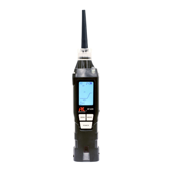
Product Components 3-1. Names and functions for each part This section describes names and functions of main unit, the battery unit parts, and the LCD display. Main unit (11) (10) Name Function Gas inlet Collects gases. Alarm LED arrays Blinks or lights up in response to an alarm. LCD display Displays gas concentrations, measured gas name, alarms, etc. - Page 11 Standard accessories Unpack and check the main unit and accessories. • AA alkaline battery (2 pcs) (installed) • Taper nozzle (1 pc) • Rubber protection cover (1 pc) (Protect the detector from shocks by being hit, etc.) • Hand strap (1 pc) •...
- Page 12 LCD display Name Function Operating state display Displays the operating status in the detection mode. Normal: Blinking Flow check display Displays the drawing status. Normal: Rotating Gas concentration Displays gas concentration and units (ppm). display Alarm sound display Displays the setting status of the alarm sound. Operation sound Displays the setting status of the operation sound.
-
Page 13: How To Use
How to Use 4-1. Before using the detector First-time users and users who have already used the detector must follow the operating precautions. Ignoring the precautions may damage the unit, resulting in inaccurate gas measurement. 4-2. Preparation for start-up Before use, read and understand the following precautions. Ignoring these may cause inaccurate gas detection. - Page 14 CAUTION • Never fail to turn off the power of the detector before replacing the batteries. • Replace the batteries in a safe place. • Replace both of the two batteries with new ones at one time. • Pay attention to the polarities during replacement. Replace while checking the battery polarities stamped on the body.
-
Page 15: How To Start The Detector
4-4. How to start the detector When the power is turned on, a self-diagnostic starts, and then the detector enters the detection mode. Power-on Press and hold the POWER button until the buzzer blips (one second or longer) to turn on the power. When the power is turned on, the LCD display changes automatically as shown below, and the detector enters the detection mode. - Page 16 NOTE • When powering on after leaving the detector for more than five minutes with the batteries removed, such as when powering on for the first time, replacing the batteries, etc., or powering on with the batteries inserted with incorrect polarities, a clock abnormality (FAIL CLOCK) may be triggered. When it is reset using the MODE button, the detector moves to the date/time setting screen.
-
Page 17: Basic Operating Procedures
4-5. Basic operating procedures The detection mode is used after power-on. Gas is detected in the ppm range. button buttons Hold down for Hold down for Hold down for 1 sec 3 secs 3 secs Illumination lamp lights <Operation/alarm sound ON/OFF> <Peak clear>... -
Page 18: How To Detect
4-6. How to detect While the detector is operating in detection mode, put the tip of the taper nozzle close to the detection area and draw sample. The detector measures gas in the ppm range. If a gas is drawn, the detected gas concentration is displayed with the bar meter on the LCD display. -
Page 19: Changing The Alarm Setpoint
4-7. Changing the alarm setpoint In the detector, the alarm setpoint is factory set to 30 ppm. The detector has 5 preset alarm setpoints that the user can cycle through (10 ppm, 30 ppm, 150 ppm, 500 ppm, and 2000 ppm). How to change the alarm setpoint 1 In the detection mode, press the AIR and MODE buttons at the same time. -
Page 20: Performing Air Calibration
4-8. Performing air calibration After a high-concentration gas is detected or an alarm is triggered by temperature/humidity changes, perform an air calibration in the measured atmosphere. * Before performing air calibration, verify a fresh air environment. In the detection mode, hold down the AIR button. -
Page 21: Snap Logger
NOTE • Perform air calibration under pressure and temperature/humidity conditions close to those in the operating environment and in fresh air. • Perform air calibration after the reading is stabilized. • If there is a sudden temperature change between the storage and operational locations, turn on the power of the detector, let it stand for five minutes or more in a similar environment to the operational location, and perform air calibration in fresh air before using it. -
Page 22: Peak Hold Function
4-10. Peak hold function When the peak hold function is enabled, the latest peak value is always displayed with the bar meter. In the detection mode, hold down the MODE button (for three seconds or longer). The peak hold function is enabled. -
Page 23: How To Turn On The Illumination Lamp
4-12. How to turn on the illumination lamp The illumination lamp can be turned on, if necessary. Hold down the AIR and POWER buttons at the same time (for three seconds or longer). The illumination lamp lights up. The illumination lamp will automatically go off two minutes after it lights up. -
Page 24: Display Mode
Display Mode 5-1. Entering the display mode This mode allows users to view and change various display settings. (Display example: For city gases) In the detection mode, press the MODE button. The detector enters the peak value display in the display mode. - Page 25 Display mode overview Item LCD display Details Peak display Displays the maximum concentration detected during the period from power-on to the point of checking. * To clear the peak display, hold down the AIR button until "PEAK CLR" is displayed. Measured gas reading By changing the setting to the setting...
-
Page 26: Measured Gas Reading Setting
5-2. Measured gas reading setting Normally, the concentration display of the detector is H2 by default; however, other combustible gases or CFC gases can be detected. For the list of possible detection gases, see the "Gas list" in the following page. On the "GAS LIST"... - Page 27 Gas list Gas name Display Grid 1 Grid 2 Grid 3 Grid 4 Grid 5 Grid 6 (standard name) 2000 10000 Methane (CAL gas) 2000 10000 Hydrogen (CAL gas) H2 2000 10000 Acetylene C2H2 2000 10000 Ethylene C2H4 2000 10000 Ethane C2H6 2000...
-
Page 28: Log Data Display
5-3. Log data display The data recorded by the snap logger can be viewed. The "REC DATA" screen is displayed only when the clock function is enabled (See "6-3. Clock function ON/OFF setting" on page 32). On the "REC DATA" screen in the display mode, press the POWER button. -
Page 29: User Mode
User Mode 6-1. Entering the user mode The maintenance including internal clock correction, etc. can be performed. In the detection mode, press the MODE button a few times to display "USER" and then press the POWER button. The detector enters the date/time setting in the user mode. - Page 30 User mode overview Item LCD display Details Date/time setting Set the date/time of the internal clock. (P. 31) * When the clock function is disabled, the date/time setting screen is not displayed. Clock function ON/OFF Enable or disable the clock function. setting ROM/SUM display Displays the program number and SUM...
-
Page 31: Date/Time Setting
6-2. Date/time setting Set the date/time of the internal clock. The date/time setting screen is displayed only when the clock function is enabled. Enable the clock function in "6-3. Clock function ON/OFF setting" on page 32 before setting the date/time. On the "DATE"... -
Page 32: Clock Function On/Off Setting
6-3. Clock function ON/OFF setting Enable or disable the clock function. The clock function is disabled by default. If the date/time needs to be displayed on start-up or the snap logger function is used, enable the clock function. On the "CLOCK" screen in the user mode, press the POWER button. -
Page 33: Alarm Function
Alarm Function 7-1. Gas alarm activation When the concentration of detected gas reaches or exceeds the alarm setpoint values, a "gas alarm" is triggered in the detector. The alarm lamp blinks, the buzzer sounds, and the bar meter display indicates an alarm condition. -
Page 34: Maintenance
Maintenance The detector is a precision device. To maintain the performance of the detector and improve the reliability of detecting leakage, perform a regular maintenance. 8-1. Maintenance intervals and items Perform the following maintenance regularly before use. ・ Daily maintenance: Perform maintenance before commencing each work. ・... - Page 35 About maintenance services We provide services on regular maintenance including span adjustment, other adjustments and maintenance. To make the calibration gas, dedicated tools, such as a gas cylinder of the specified concentration, gas sampling bag, etc., must be used. Our qualified service engineers have expertise, knowledge and other information on the dedicated tools used for services, along with other products.
-
Page 36: How To Clean
8-2. How to clean Clean the detector if it becomes extremely dirty. The detector must be turned off while cleaning it. Use a waste cloth or the like to remove dust. Do not use water or organic solvent for cleaning because they may cause malfunctions. - Page 37 Replace the hydrophobic filter with a new one. Make sure it’s seated in the rubber seal correctly. Hydrophobic Filter Rubber seal Attach the rubber seal, with the hydrophobic filter installed, to the cap. Make sure the rubber seal’s rib has been firmly inserted into the cap’s groove.
- Page 38 Interference gas removal filter (CF-8392) replacement procedure The interference gas removal filter (CF-8392) is installed to the detector to remove interference gases that damage sensors for silicone, sulfides, etc. Continuing to use the detector may cause the filter to be contaminated or clogged. Replace the filter when it has absorbed water or oil, etc.
-
Page 39: Calibration Mode
9-1. Fresh Air Adjustment RKI Instruments, Inc. recommends that the fresh air adjustment be performed in a fresh air area (area known to be free of toxic and combustible gases and of normal oxygen content, 20.9%). If a fresh air environment is not available, a cylinder of zero air can be used as long as the gas is applied through a humidifier tube. - Page 40 4 The AIR CAL menu item will be displayed. 5 Press and release the POWER button. 6 Make sure you are in a fresh air area (area known to be free of toxic and combustible gases and of normal oxygen content, 20.9%).
-
Page 41: Preparing For A Span Adjustment (Gas Bag)
9 See the following sections for span adjustment descriptions. To return to Detection Mode without performing a span adjustment, scroll to the MEASURE menu item and press and release the POWER button. To turn the instrument off, press and hold the POWER. 9-2. -
Page 42: Preparing For A Span Adjustment (Demand Flow Regulator)
9-3. Preparing for a Span Adjustment (Demand Flow Regulator) This section describes how to prepare for calibration if you are using a calibration kit that includes: • Demand flow regulator • Calibration tubing • Methane calibration cylinder • Hydrogen calibration cylinder 1. - Page 43 Use the AIR and MODE buttons to adjust each character and press the POWER button to move to the next character. The AIR CAL menu item will be displayed. Use the AIR or MODE button to scroll to the AUTO CAL menu item. Press and release the POWER button.
- Page 44 To adjust the auto cal value: a. Press and hold the button then MODE press and hold the button. The POWER auto cal value will begin to flash. b. Use the buttons to MODE adjust the value. c. Press the POWER button to confirm the change.
- Page 45 14 Depending on what calibration kit you are using, you need to either: a. Empty the gas bag and refill it with H2 as described in “Preparing for a Span Adjustment (Gas Bag)” or b. Unscrew the demand flow regulator from the CH4 cylinder and screw it onto the H2 cylinder.
- Page 46 18 Press and release the POWER button. The gas reading will begin to flash. 19 Apply calibration gas for 1 minute. Depending on your calibration kit, you will need to either: a. Connect the gas bag tubing to the instrument’s inlet or b.
-
Page 47: Manual Span Adjustment
9-5. Manual Span Adjustment These instructions describe a manual calibration of the SP-220. This version of the SP-220 must be calibrated with both methane (CH4) and hydrogen (H2). Be sure you have performed a fresh air adjustment and prepared for calibration as described in the previous sections before continuing. Prepare a methane gas bag or methane calibration cylinder as... - Page 48 The AIR CAL menu item will be displayed. Use the AIR or MODE button to scroll to the MANU_CAL menu item. Press and release the POWER button. CH4 will be displayed. This version of the SP-220 needs to be calibrated to both methane (CH4) and hydrogen (H2).
- Page 49 Apply calibration gas for 1 minute. Depending on your calibration kit, you will need to either: a. Connect the gas bag tubing to the instrument’s inlet or b. Connect the tubing from the demand flow regulator to the instrument’s inlet. 10 Use the AIR and MODE buttons to adjust the gas reading to match...
- Page 50 14 Press and release the POWER button. CH4 will be displayed. This version of the SP-220 needs to be calibrated to both methane (CH4) and hydrogen (H2). Use the AIR or MODE button to toggle between the two gas selections. 15 With H2 displayed, press and release the POWER button.
-
Page 51: Password
19 Disconnect the calibration gas source from the instrument’s inlet fitting. 20 To enter Detection Mode, scroll to the MEASURE menu item and press and release the POWER button. To turn off the instrument, press and hold the POWER button. 9-6. - Page 52 The AIR CAL menu item will be displayed. Use the AIR or MODE button to scroll to the PASSWORD menu item. Press and release the POWER button. The current setting will be displayed. Use the AIR or MODE button to adjust the on/off setting.
- Page 53 To enter Detection Mode, scroll to the MEASURE menu item and press and release the POWER button. To turn off the instrument, press and hold the POWER button. - 53 -...
-
Page 54: Storage And Disposal
Storage and Disposal 10-1. Procedures to store the detector or leave it for a long time The detector must be stored under the following environmental conditions. • In a dark place under the normal temperature and humidity away from direct sunlight •... -
Page 55: Disposal Of Products
10-3. Disposal of products When the detector is disposed of, it must be treated properly as an industrial waste in accordance with the local regulations, etc. WARNING • Dispose of dry batteries in accordance with procedure specified by the local authority. <Disposal in EU Member States>... -
Page 56: Troubleshooting
Troubleshooting The Troubleshooting does not explain the causes of all the malfunctions which occur on the detector. This simply helps to find the causes of malfunctions which may frequently occur. If the detector shows a symptom which is not explained in this manual, or still has malfunctions even though remedial actions are taken, please contact RKI. - Page 57 Symptoms Causes Actions FAIL AIR CAL Make a setting of date/time. If such a symptom is observed repeatedly, Clock abnormalities Abnormalities of the internal the built-in clock is seemingly FAIL CLOCK clock malfunctioning. Thus, it must be replaced. Contact RKI for repair. Pump abnormalities Abnormalities of the pump Contact RKI for repair.
-
Page 58: Spare Parts List
Spare Parts List Part Number Description 06-1248RK-03 Calibration tubing, 3 feet 81-0000RK-21 Calibration cylinder, 2000 ppm hydrogen in air, 34 liter steel 81-0010RK-01 Calibration cylinder, 5000 ppm methane in air, 34 liter steel 81-1001RK Dispensing valve, without knob, for 17 liter and 34 liter steel cylinders (cylinders with external threads) 81-1054RK Regulator, demand flow, 0.5 LPM with gauge and knob, for 34 liter aluminum, 58 liter,... -
Page 59: Product Specifications
Product Specifications Model SP-220(TYPE H2) Detection principle Hot-wire semiconductor Gas to be detected Hydrogen * As to the other reading gaseous species, refer to Gas list. Calibration gas H2 or CH4 calibration * two gas calibration required Concentration LCD bar meter + grid display Detection range 10 - 10000 ppm... - Page 60 Error! Use the Home tab to apply 見出し 1 to the text that you want to appear here. Error! Use the Home tab to apply 見出し 2 to the text that you want to appear here. - 60 -...
Need help?
Do you have a question about the SP-220 TYPEH2 and is the answer not in the manual?
Questions and answers