Table of Contents
Advertisement
Quick Links
Advertisement
Table of Contents

Subscribe to Our Youtube Channel
Summary of Contents for Ruijie RG-AP130(W2)
- Page 1 RG-AP130(W2) Series Access Point Hardware Installation and Reference Guide V1.02...
- Page 2 Ruijie Networks reserves all copyrights of this document. Any reproduction, excerption, backup, modification, transmission, translation or commercial use of this document or any portion of this document, in any form or by any means, without the prior written consent of Ruijie Networks is prohibited. Exemption statement This document is provided “as is”.
- Page 3 It is intended for the users who have some experience in installing and maintaining network hardware. At the same time, it is assumed that the users are already familiar with the related terms and concepts. Obtaining Technical Assistance Ruijie Networks Website: https://www.ruijienetworks.com/ Technical Support Website: https://ruijienetworks.com/support...
-
Page 4: Product Overview
· 1 Product Overview Ruijie RG-AP130(W2) Wall AP is designed for wireless deployment in hotels, offices, residential buildings and settings alike. The wall-mountable AP integrates Ethernet and VoIP ports. Featuring a concise design and easy deployment, the AP enables zero disruption to the interior finishes and offers the best solution for scenarios with delicate interior design. - Page 5 Hardware Installation and Reference Guide Product Overview Adjustment · Dimensions 116mm x 86mm x 42mm (4.6in x 3.4in x 1.7in) (W x D x H) Weight 0.23kg Front: Four 10/100/1000Base-T LAN ports Side: Service Ports One RJ-45 Voice/PoE pass-through port (RJ-11 combo) Rear: One 10/100/1000Base-T WAN port One RJ-45 Voice/PoE pass-through port (RJ-11 combo)
-
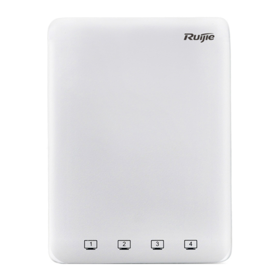
Page 6: Product Image
Hardware Installation and Reference Guide Product Overview Rogue AP detection and countermeasure Support · Dynamic ACL assignment Support RADIUS Support CPU Protection Policy (CPP) Support Network Foundation Protection Policy (NFPP) Support IPv4 address Support IPv6 CAPWAP tunnel Static IP address or DHCP ICMPv6 Support IPv6 address... -
Page 7: Led Indicators
Hardware Installation and Reference Guide Product Overview · Note 1. Reset button 4. Keyhole 2. Lock Slot 5. Pass Through port on the side 3. Micro USB management port (Console) 6. DC power adapter port (for DC power supply) 1.3 LED Indicators Figure 1-3 Indicator on the AP State Frequency... -
Page 8: Power Sources
Internal: positive External: negative When powered through PoE, the AP can be used with Ruijie’s other products supporting 802.3af PoE. 1.5 Cooling Solution The AP adopts fanless design. Because it is installed in an 86-style faceplate on the wall, to guarantee airflow for proper... -
Page 9: Preparing For Installation
Hardware Installation and Reference Guide Preparing for Installation · 2 Preparing for Installation 2.1 Safety Suggestions RG-AP130(W2) must be used inside the room. To ensure normal operation and a prolonged useful life of the equipment, the installation site must meet the following requirements. To prevent device damage and bodily injury, please read carefully the safety recommendations described in this chapter. -
Page 10: Emi Consideration
Hardware Installation and Reference Guide Preparing for Installation (Particles/m · Besides, the contents of salts, acids and sulfides in the air are also strictly limited for the equipment room. These substances can accelerate metal corrosion and the aging of some parts. Table 2-3 describes the limit of some hazardous gases such as SO S, NO and Cl... -
Page 11: Installing The Access Point
Hardware Installation and Reference Guide Installing the Access Point · 3 Installing the Access Point Make sure you have carefully read Chapter 2, and be sure that the requirements set forth in Chapter 2 have been met. 3.1 Installation Flowchart 3.2 Before You Begin To ensure normal operation and a prolonged useful life of the equipment, observe the following safety precautions: ... - Page 12 Hardware Installation and Reference Guide Installing the Access Point Keep the device clean and dust-free. · Disconnect the device before cleaning it. Do not wipe the device with a damp cloth. Do not wash the device with liquid. ...
- Page 13 Hardware Installation and Reference Guide Installing the Access Point · Align screw holes on both sides of the device over those on the faceplate. And then tighten screws with a screwdriver. Figure 3-3 Tighten Screws with a Screwdriver Install the plate cover in the way as shown in the following figure. Figure 3-4 Install the Cover...
- Page 14 Hardware Installation and Reference Guide Installing the Access Point · A white cover is provided for each AP. And there are three more options for sale: black, gold and silver. Figure 3-5 Cover for RG-AP130(W2)
-
Page 15: System Debugging
Hardware Installation and Reference Guide System Debugging · 4 System Debugging 4.1 Setting up a Debugging Environment Use PoE to power the AP. PoE power supply To use a PoE device, make sure the peer end supports the IEEE 802.3af PoE standard. Then, connect the Ethernet cable to the uplink port (WAN) on the AP. -
Page 16: System Reset
Hardware Installation and Reference Guide System Debugging · 4.1.2 Reset/Restore Default Settings The reset button is hidden in a hole and used by technical support personnel. To avoid abnormal operation, do not use this button without consultation with technical support personnel. Figure 4-3 Reset Button on the AP 4.1.3 System Reset Remove the cover. -
Page 17: Monitoring And Maintenance
Hardware Installation and Reference Guide Monitoring and Maintenance · 5 Monitoring and Maintenance 5.1 Monitoring You can observe the LED to monitor the AP in operation. Fast blinking green followed by solid green: The AP is being initialized and is operational. ... -
Page 18: Troubleshooting Flowchart
Hardware Installation and Reference Guide Troubleshooting · 6 Troubleshooting 6.1 Troubleshooting Flowchart 6.2 Troubleshooting LED does not light up after the AP is powered on Verify that the power source is IEEE 802.11af compliant. And then verify that the cable is connected properly. Orange LED blinks after the Ethernet cable is connected Verify that the device at the other end of the Ethernet cable is working properly. -
Page 19: Appendix A Connectors And Media
Hardware Installation and Reference Guide Appendix A Connectors and Media · Appendix A Connectors and Media 1000BASE-T/100BASE-TX/10BASE-T The 1000BASE-T/100BASE-TX/10BASE-T is a 10/100/1000 Mbps auto-negotiation port that supports auto MDI/MDIX. Compliant with IEEE 802.3ab, 1000BASE-T requires Category 5e 100-ohm UTP or STP (STP is recommended) with a maximum distance of 100 meters (328 feet). - Page 20 Hardware Installation and Reference Guide Appendix A Connectors and Media ·...
Need help?
Do you have a question about the RG-AP130(W2) and is the answer not in the manual?
Questions and answers